Carriage-mounted unit of weft knitting machine

A technology of tripod carriage and flat knitting machine, which is applied in textile and papermaking, weft knitting, knitting and other directions, can solve the problems that the miniaturization and light weight of tripod carriage cannot be realized.

Active Publication Date: 2008-11-19
SHIMA SEIKI MFG LTD
View PDF3 Cites 13 Cited by
  • Summary
  • Abstract
  • Description
  • Claims
  • Application Information

AI Technical Summary

Problems solved by technology

However, if the carriage mounting unit is larg...

Method used


Image

  • Carriage-mounted unit of weft knitting machine
  • Carriage-mounted unit of weft knitting machine
  • Carriage-mounted unit of weft knitting machine

Examples


Embodiment Construction

[0029] Hereinafter, the preferred embodiments of the present invention will be described in detail with reference to the drawings.

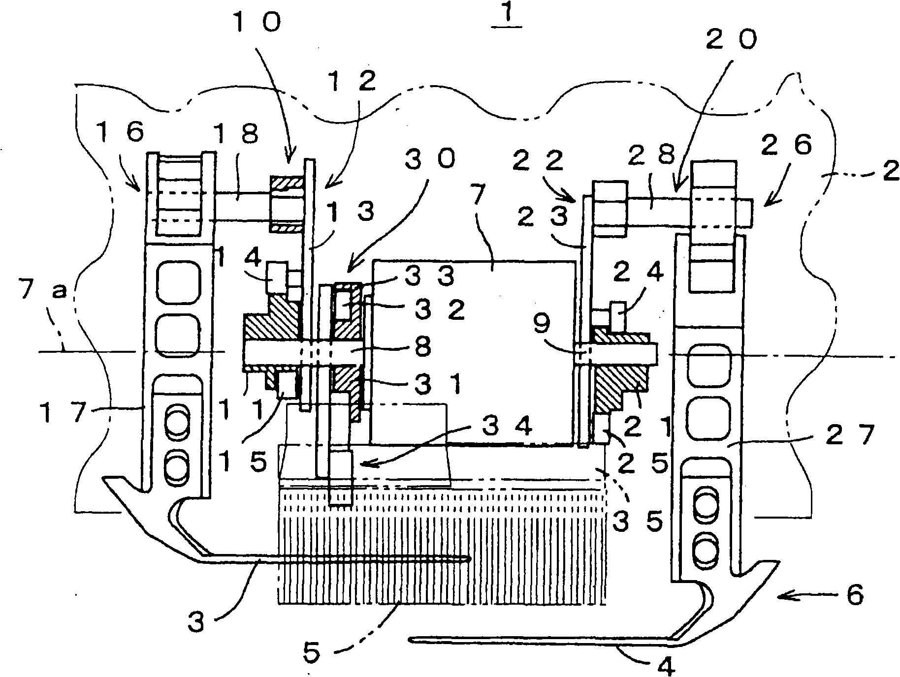
[0030] figure 1 The schematic structure of the drive unit 1 as an embodiment of the present invention is shown. The drive unit 1 is mounted on a carriage 2 that reciprocates along the needle bed of the flat knitting machine, and functions as a carriage mounting unit of the flat knitting machine. The carriage 2 performs selective driving for knitting the knitted fabric by retreating the knitting needles from the needle bed. The drive unit 1 includes a pair of components that can be switched according to the moving direction of the carriage 2 and has at least three components that can advance and retract independently of the knitting needles. That is, a pair of pressure needle plates 3, 4, that is, one needle pressure plate 3 and the other needle pressure plate 4 can be switched between each other according to the movement of the carriage 2 in the lef...


PUM


Abstract

A carriage-mounted unit of a weft knitting machine enabling a reduction in size even if it has a large number of functions. A pair of stitch pressers (3, 4) are driven by the rotating motion of a motor (7) through one side drive mechanism (10) and the other side drive mechanism (20). The one side drive mechanism (10) and the other side drive mechanism (20) is provided with double-lift cams (11) and (21) to reduce a load on the motor (7). A cam drive mechanism (30) advances and retreats a bristle (5) being the other member to and from a trick gap part (6) so as to avoid its interference with the pair of stitch pressers (3, 4). Even if at least three of stitch pressers (3, 4) being a pair of members and the bristle (5) being the other member are so driven by the single motor (7) that each of these members is advanced to and retreated from the trick gap part (6) by the rotation of the motor (7), a part such as a groove cam plate reciprocating in the reciprocating direction of a carriage (2) is not provided in the unit, and therefore, the unit can be small-sized.

Description

Technical field [0001] The present invention relates to a carriage carriage mounting unit for a flat knitting machine which is mounted on a carriage carriage of a flat knitting machine and drives various components to advance and retreat with respect to a gear opening. Background technique [0002] Conventionally, in a flat knitting machine, a plurality of needle grooves are formed on a needle bed extending linearly along the tooth gap to accommodate knitting needles. The knitting of the knitted fabric is performed by, for example, reciprocating the carriage along the needle bed, and moving the knitting needles forward and backward relative to the tooth gap by a cam mechanism mounted on the carriage. In the tooth gap, the knitting yarn from the yarn feeding member linked with the carriage is supplied to the tip of the knitting needle that enters from the needle bed. Knitting loops by introducing knitting needles into the needle bed. As the basic stitch formation, when the knittin...

Claims


Application Information

Patent Timeline
IPC IPC(8): D04B15/06D04B15/00D04B15/08D04B15/90
CPCD04B15/90
Inventor 宫本昌纪
Owner SHIMA SEIKI MFG LTD
Why Eureka
Try Eureka