Body cavity probe apparatus

A technology for detecting devices and body cavities, applied to endoscopes, diagnostic recording/measurement, catheters, etc., can solve the problems of large radiation damage, inability to generate real-time image-guided images, and structures that do not record the direction of real-time image detection , to achieve the effect of reducing radiation damage

Inactive Publication Date: 2008-01-02
OLYMPUS CORP
View PDF2 Cites 16 Cited by
  • Summary
  • Abstract
  • Description
  • Claims
  • Application Information

AI Technical Summary

Problems solved by technology

[0010] The first does not describe the structure of detecting the insertion shape
Therefore, there is a problem that a guide image including an inserted shape cannot be generated
[0011] The second does not describe the structure of detecting the direction of the real-time image
[0015] However, in the body cavity detection device disclosed in Japanese Patent Application Laid-Open No. 2002-306403, gamma rays are used to detect the insertion shape, and a new problem arises in that radiation damages both the doctor and the subject greatly.
[0016] Second, regarding the problem of not being able to generate a guide image including the direction of the real-time image, Japanese Patent Application Laid-Open No. 2002-306403 does not describe a structure for detecting the direction of the real-time image, and this problem cannot be solved.

Method used


Image

  • Body cavity probe apparatus
  • Body cavity probe apparatus
  • Body cavity probe apparatus

Examples


Embodiment 1

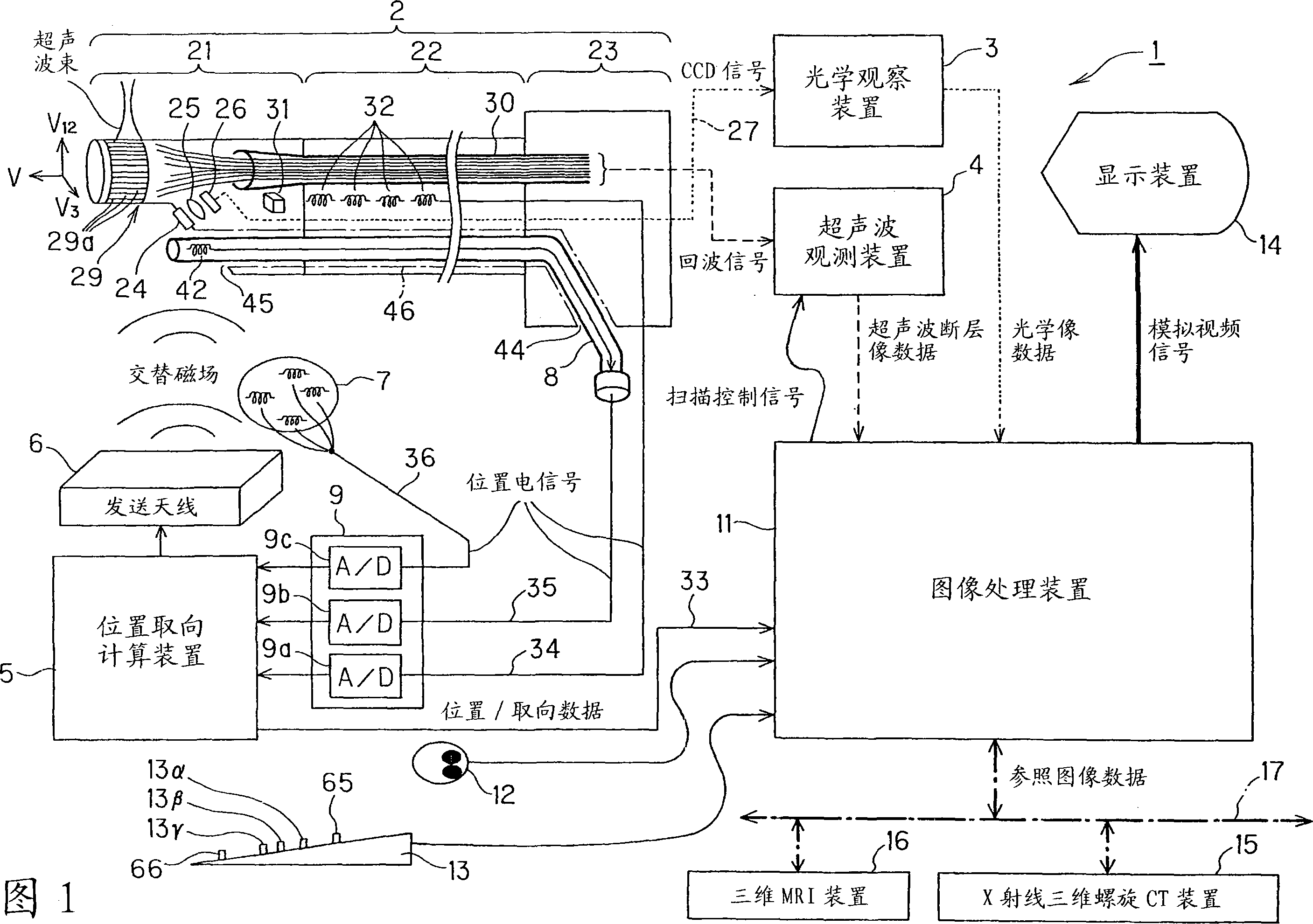
[0052] Embodiment 1 of the present invention will be described with reference to FIGS. 1 to 21 . First, the configuration of the intra-body cavity detection device 1 according to the first embodiment of the present invention will be described.

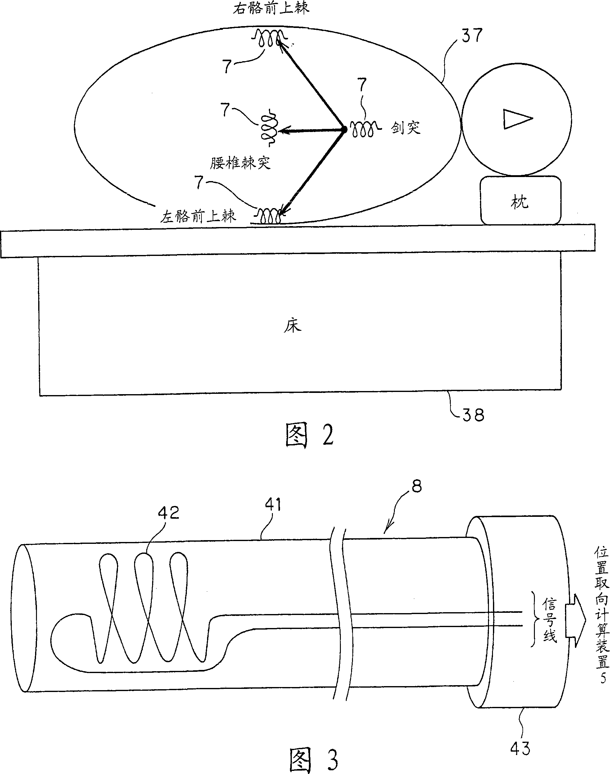
[0053] As shown in Figure 1, the body cavity detection device 1 of Embodiment 1 includes: an electronic radial scanning ultrasonic endoscope 2 as a body cavity detector, an optical observation device 3, an ultrasonic observation device 4, a position and orientation calculation device 5, Transmitting antenna 6, body surface detection coil 7, body cavity contact detector 8, A / D unit 9, image processing device 11, mouse 12, keyboard 13, and display device 14 are connected by signal lines.

[0054] An X-ray three-dimensional helical CT device (X-ray 3dimentional computer tomography system) 15, a three-dimensional MRI device (3 dimentionalmagnetic resonance imaging system) 16, and fast networks such as optical communication and ADSL connect...

Embodiment 2

[0335] Next, Embodiment 2 of the present invention will be described. The structure of this embodiment is the same as that of Embodiment 1. However, only the function of the three-dimensional guide image generation circuit B is different from that of the first embodiment.

[0336] Next, the action of this embodiment will be described.

[0337] As described above, this embodiment differs from Embodiment 1 only in the function of the three-dimensional guide image generating circuit B.

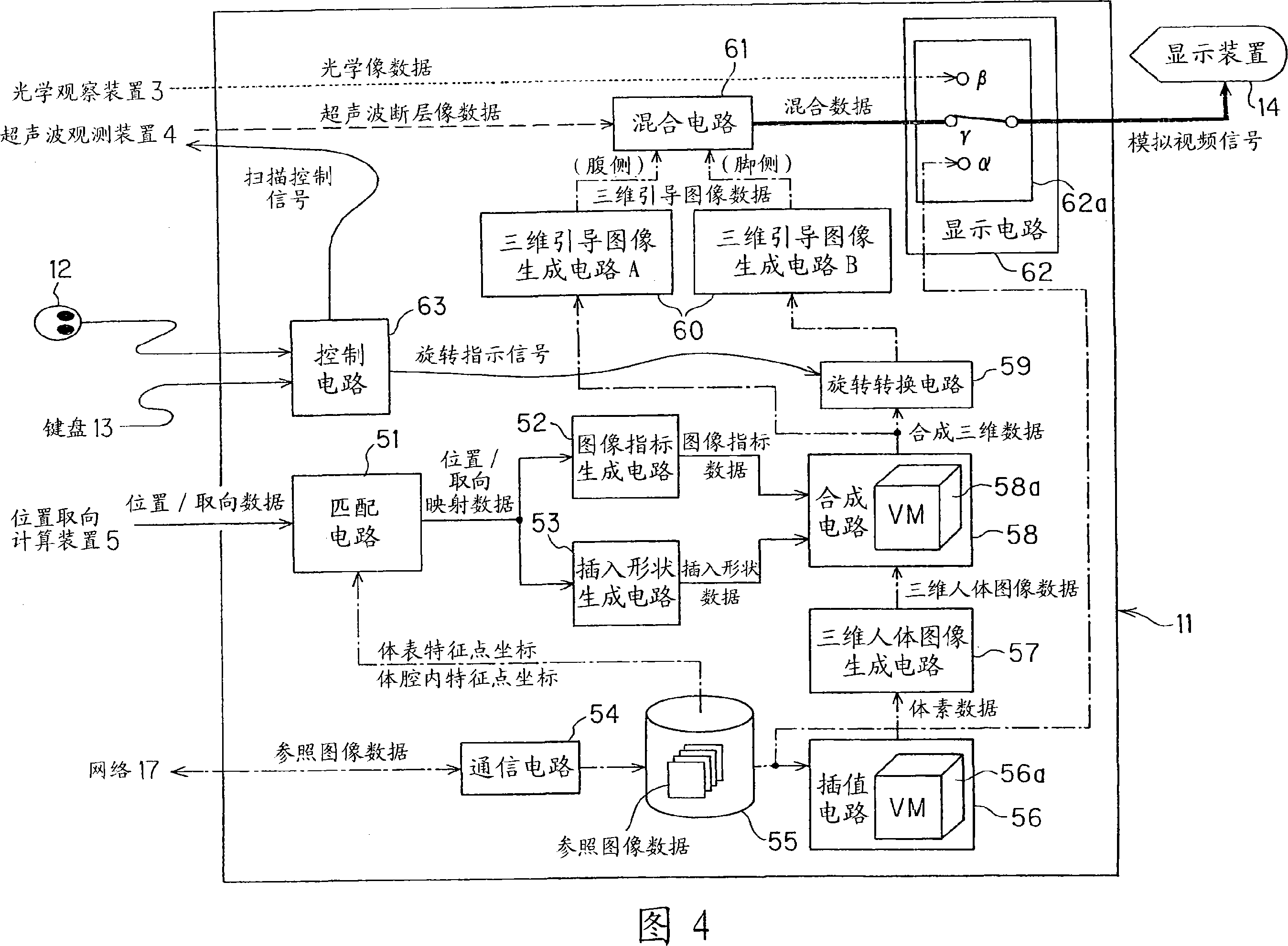
[0338] In Embodiment 1, as shown in FIG. 15 , the three-dimensional guide image generating circuit B generates three-dimensional guide image data viewed from the direction of the subject's feet, and outputs the data to the mixing circuit 61 .

[0339] In addition, along with the movement of the radial scanning plane accompanying the manual manipulation of the flexible part 22 and the rigid part 21 by the doctor, the ultrasonic tomographic image marker Mu, the distal end direction marker Md, the...

Embodiment 3

[0351] Next, Embodiment 3 of the present invention will be described.

[0352] The structure of this embodiment is the same as that of Embodiment 2. Only the function of the three-dimensional guide image generating circuit B in this embodiment is different from that in Embodiment 2.

[0353] Next, the action of this embodiment will be described.

[0354] As described above, the present embodiment differs from the second embodiment only in the function of the three-dimensional guide image generating circuit B.

[0355] In Embodiment 2, as shown in FIG. 22, the three-dimensional guide image generation circuit B makes the ultrasonic tomographic marker Mu in the image index data translucent, so that the six o'clock direction marker Mt and the direction of the tip of the image index data can be seen through. The mark Md, and the insertion shape mark Ms and the coil position mark Mc of the insertion shape data, for other organs, make the ultrasonic tomographic image mark Mu opaque...


PUM


Abstract

A body cavity probe apparatus can minimally invasively detect the insertion shape of a body cavity probe and the direction of real-time images to create guide images each containing both the insertion shape of the body cavity probe and the direction of the real-time image. An ultrasonic endoscope as a body cavity probe inserted into the body cavity has an ultrasonic transducer array in a rigid portion located at a distal end thereof, to acquire an ultrasonic echo signal, an image position and orientation detecting coil provided in the vicinity of the ultrasonic transducer array, and an insertion shape detecting coil provided in a longitudinal direction of the flexible portion, thus generating guide images each containing the shape of the flexible portion and the direction of an ultrasonic tomogram generated from the echo signal as a real-time image.

Description

technical field [0001] The present invention relates to an intrabody cavity detection device for diagnosing the inside of a body cavity, etc., using an intrabody probe inserted into a body cavity. Background technique [0002] Conventionally known probes in body cavities such as endoscopes, ultrasonic endoscopes, and narrow-diameter ultrasonic probes are inserted into body cavities such as digestive tracts, bile-pancreatic ducts, and blood vessels for diagnosis and treatment. These body cavity probes are usually equipped with imaging elements such as CCD cameras or ultrasonic vibrators at the front end. [0003] Furthermore, these intrabody cavity probes are conventionally used as an intrabody cavity detection device integrated with a processor that generates an optical image or an ultrasonic tomographic image based on a signal obtained from an imaging element or an ultrasonic vibrator. [0004] In addition, the body cavity detection devices known in recent years have a gui...

Claims


Application Information

Patent Timeline
Patent Type & Authority Applications(China)
IPC IPC(8): A61B1/00A61B8/12
CPCA61B1/042A61B8/4488A61B6/5247A61B6/466A61B5/065A61B5/06A61B8/463A61B6/032A61B5/055A61B8/4254A61B8/467A61B8/5238A61B8/12A61B1/0051A61B8/466A61B8/4444
Inventor 川岛知直生熊聪一小幡里织小室雅彦
Owner OLYMPUS CORP
Why Eureka
Try Eureka