Temperature regulation of the mass flow in a filling machine

A technology of temperature control and filling machine, applied in the direction of temperature control, non-electric variable control, control/regulation system, etc.

A technology of temperature control and filling machine, applied in the direction of temperature control, non-electric variable control, control/regulation system, etc.

CN101313691AActive Publication Date: 2008-12-03ALBERT HANDTMANN MASCHFABRICK

Image

  • Temperature regulation of the mass flow in a filling machine
  • Temperature regulation of the mass flow in a filling machine
  • Temperature regulation of the mass flow in a filling machine

Examples


Embodiment Construction

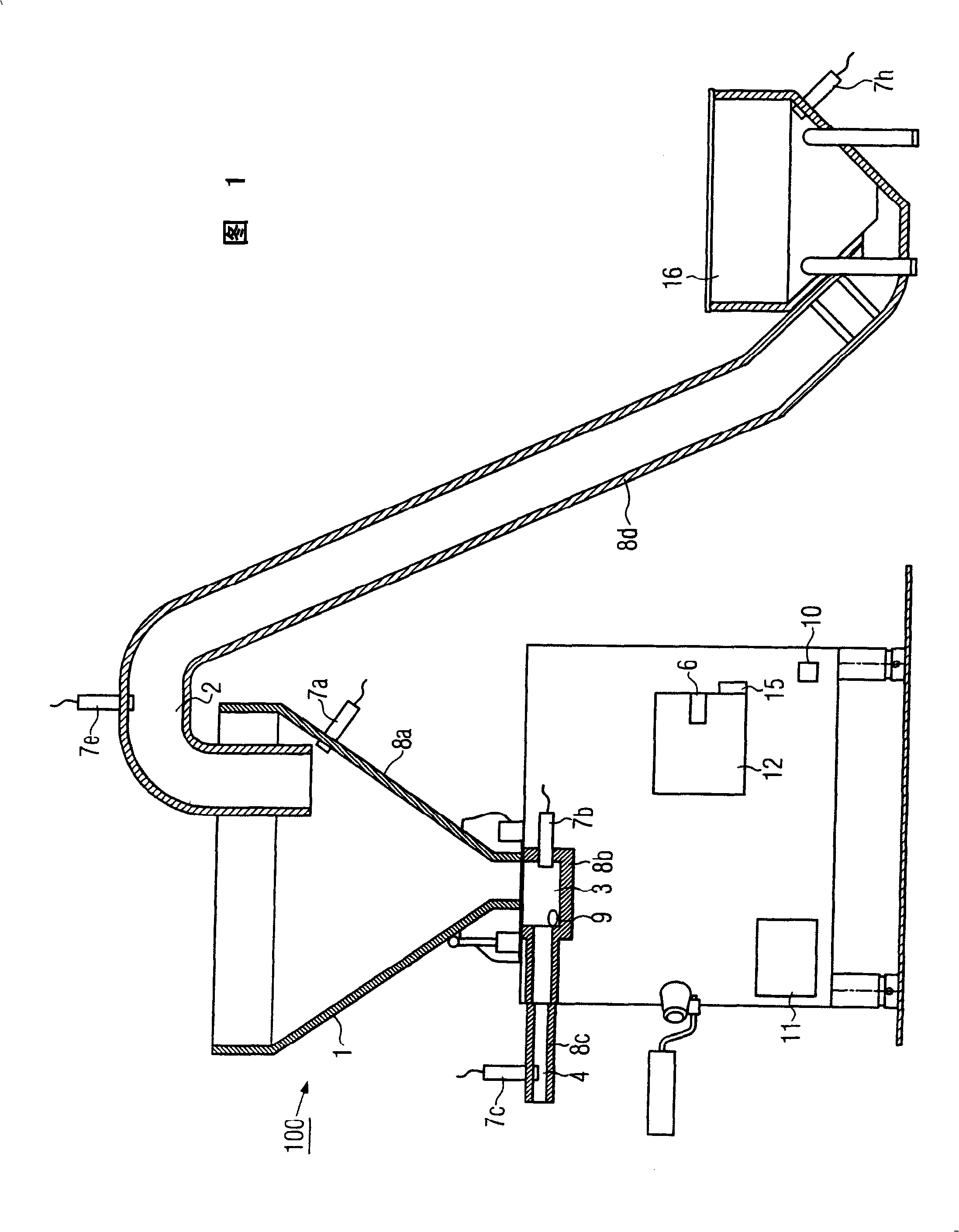
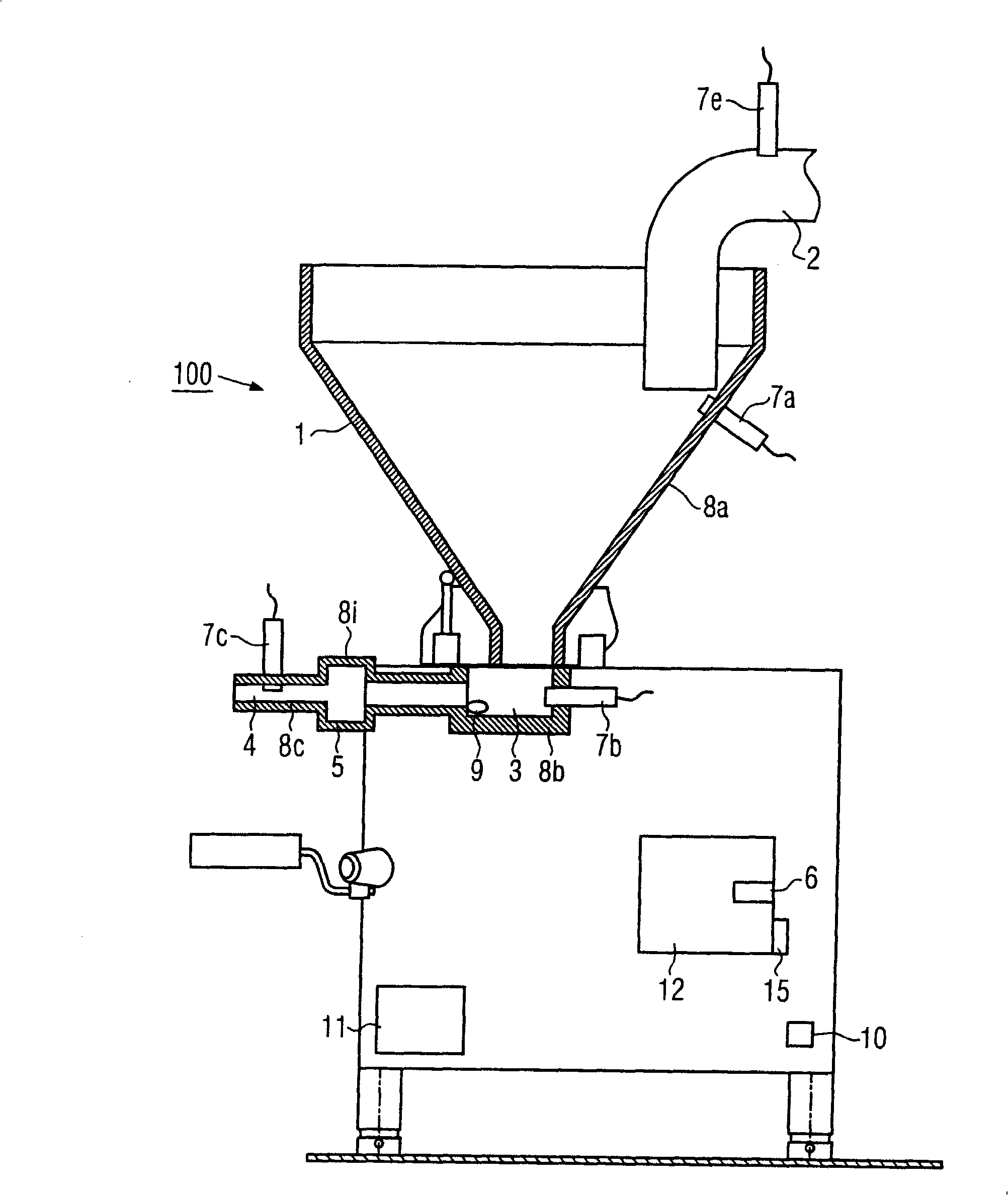
[0030] Figure 1 shows an embodiment of a filling machine 100 of the present invention. The filling machine 100 includes a filling hopper 1, such as a vacuum hopper, in which negative pressure can be generated. In addition, the filling machine 100 comprises a suction pipe 2 , through which a pasty substance, hereinafter also referred to as filling, can be fed into the filling hopper 1 . The suction tube 2 is part of the suction inlet part for the filling. The previous floor mounted hopper 16 may also be included in the suction inlet assembly. In addition, the filling machine also includes a conveying mechanism 3 arranged at the lower end of the conical filling hopper 1 . In a conventional manner, such a conveying mechanism 3 comprises, for example, a vane pump or a screw pump which extrudes the filling material out of the stuffing hopper 1 in the direction of the filling pipe 4 through which the filling material is squeezed into the sausage casing.

[0031] The filling machi...


PUM


Abstract

The method involves passing a mass flow over multiple regions of a filling machine (100). Temperature of the mass flow or of components flowing through the mass flow is measured within the regions of the filling machine. The temperature of the mass flow is controlled to a predetermined temperature by a heating / cooling device based on the measured temperature. The temperature is measured within a region of a filling hopper (1) or an intake region (2) and adjacent to a conveying system (3). An independent claim is also included for a filling machine comprising a filling machine.

Description

technical field [0001] The invention relates to a method and a filling machine according to the preambles of claims 1 and 14 . Background technique [0002] Stuffing machines of this type for filling sausage casings with pasty substances are known. During the processing of certain types of fillings, such as fermented sausages, it should be ensured that the temperature of the filling does not fall below or exceed a certain temperature throughout the processing chain. If the filling falls below or exceeds a certain temperature, then it cannot be processed further. Therefore, the temperature of the stream is usually captured, and once it reaches a certain limit, the operator must actively and manually intervene in the production process. With a heated hopper, intervention is possible as long as the filling is in the hopper. It may even be necessary to interrupt production to remove the filling from the machine, since it can no longer be processed. However, removing the fill...

Claims


Application Information

Patent Timeline
03 Dec 2008
Publication
CN101313691A
IPC
A22C11/02; G05D23/00; A23L13/00
CPC
A22C11/0245
Inventors
B·梅勒; P·韦尔伯格