
Method for operating an operating device for a motor vehicle

A technology for operating equipment, motor vehicles, in the direction of input/output processes of data processing, instruments, measuring devices, etc.

Inactive Publication Date: 2014-12-17
AUDI AG
View PDF10 Cites 0 Cited by
  • Summary
  • Abstract
  • Description
  • Claims
  • Application Information

AI Technical Summary

Problems solved by technology

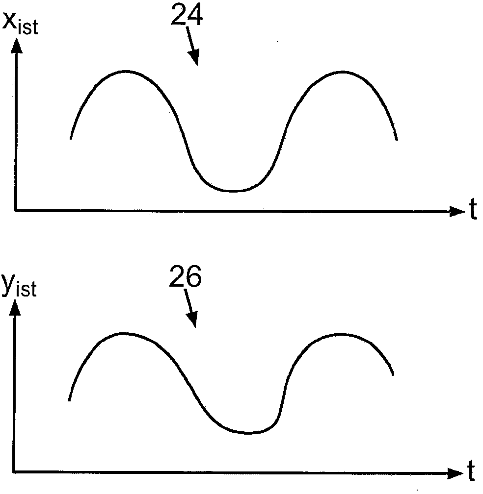
This results in a modulation of the output voltage of the photosensor's analog

Method used


Image

  • Method for operating an operating device for a motor vehicle
  • Method for operating an operating device for a motor vehicle
  • Method for operating an operating device for a motor vehicle

Examples


Embodiment Construction

[0030] The examples described in detail below are preferred embodiments of the present invention.

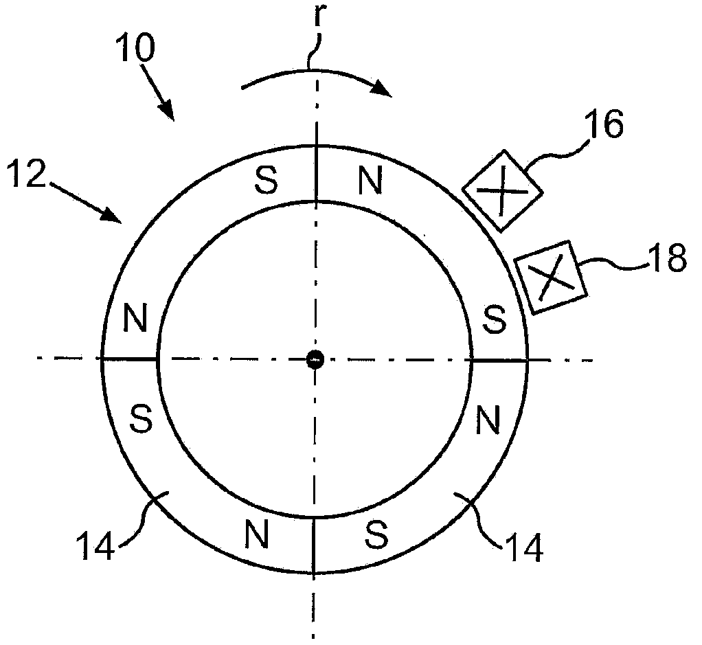
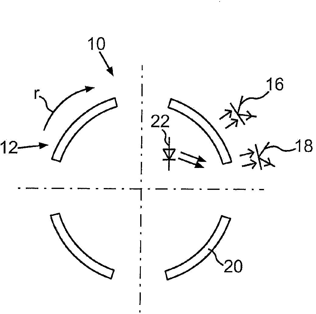
[0031] figure 1 A schematic illustration of an operating device 10 for a motor vehicle is shown in plan view. The operating device 10 serves to operate functional devices of the motor vehicle. Such functional devices may be air conditioning systems, navigation systems, operating devices with associated displays, entertainment systems or the like. The operating device 10 includes a rotary adjuster, which is rotatably mounted on a holding element (not shown here). The operating device 10 has a locking device, by means of which a plurality of locking stages are predetermined for the rotary actuator along the direction of rotation r.

[0032] Furthermore, the operating device 10 includes a coding element 12 . The coding element 12 can be arranged on the rotary adjuster. Currently, the coding element 12 is formed by four permanent magnets 14 which are arranged along the circumfe...


PUM


Abstract

The invention relates to a method for operating an operating device (10) for a motor vehicle, wherein the operating device (10) is a rotary actuator, which is rotatably mounted on a holding element and has a coding element (12), by detecting a first actual sensor value (xist) by using a coding of the coding element (12) in the current rotational position of the rotary actuator, determining a current rotational angle ([alpha]) between the rotary position and the holding element on the basis of the detected first actual sensor value (xist, yist), respectively providing at least one intended sensor value (xsoll, ysoll) relating to predetermined rotational angles ([alpha]) between the rotary position and the holding element, assigning the detected first actual sensor value (xist) to one of the at least one intended sensor values (xsoll, ysoll), and matching the first actual sensor value (xist) to the intended sensor value (xsoll, ysoll) assigned thereto for the determination of the current rotational angle ([alpha]).

Description

technical field [0001] The invention relates to a method for operating an operating device of a motor vehicle. The invention also relates to an operating device for a motor vehicle. Background technique [0002] Corresponding operating devices are provided for operating functional devices of the motor vehicle. The operating device may comprise a rotary regulator or a rotary encoder. Today's rotary adjusters have mechanical latching positions into which the rotary adjuster snaps in along its direction of rotation. These latching positions can be sensed by the user or operator by touch. Such manual rotary controls have been used millions of times over the years and are used, for example, as volume controls, in air conditioning operating components or in central input units in motor vehicles. Rotary regulators generally have corresponding coding elements that can be detected by sensors. The coding element can comprise one or more magnets, which are detected via Hall sensor...

Claims


Application Information

Patent Timeline
IPC IPC(8): G01D5/245G01D5/347
CPCG01D5/245G01D5/3473G06F3/0362
Inventor S·迈瓦尔德J·克鲁格
Owner AUDI AG
Learn More