Method of servo-control in a braking system having electric brakes

a technology of electric brakes and braking systems, which is applied in the direction of braking systems, process and machine control, instruments, etc., can solve the problems of friction element wear and tear in the relationship, and achieve the effect of reducing friction element wear and tear

Active Publication Date: 2008-03-18
SAFRAN LANDING SYSTEMS
View PDF5 Cites 10 Cited by
  • Summary
  • Abstract
  • Description
  • Claims
  • Application Information

AI Technical Summary

Benefits of technology

[0011]An object of the invention is to provide a method for countering a possible drop in servo-control performance during the lifetime of a brake.BRIEF DESCRIPTION OF THE INVENTION
[0013]It has been found that this relationship is very sensitive to friction element wear. Adjusting the relationship in accordance with the invention makes it possible to compensate drift in the operating conditions of the brake due to said friction element wear.

Problems solved by technology

It has been found that this relationship is very sensitive to friction element wear.

Method used


Image

  • Method of servo-control in a braking system having electric brakes
  • Method of servo-control in a braking system having electric brakes
  • Method of servo-control in a braking system having electric brakes

Examples


Embodiment Construction

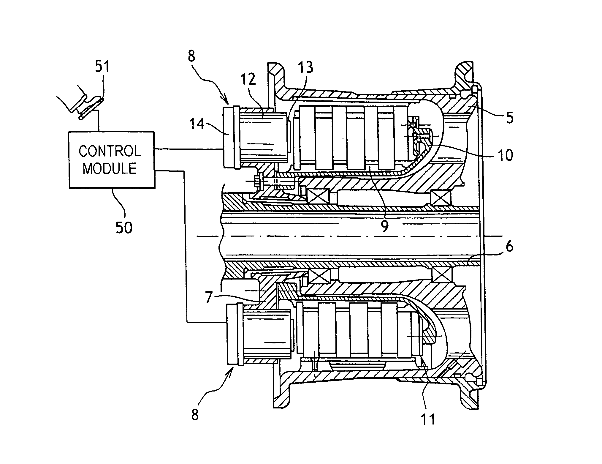
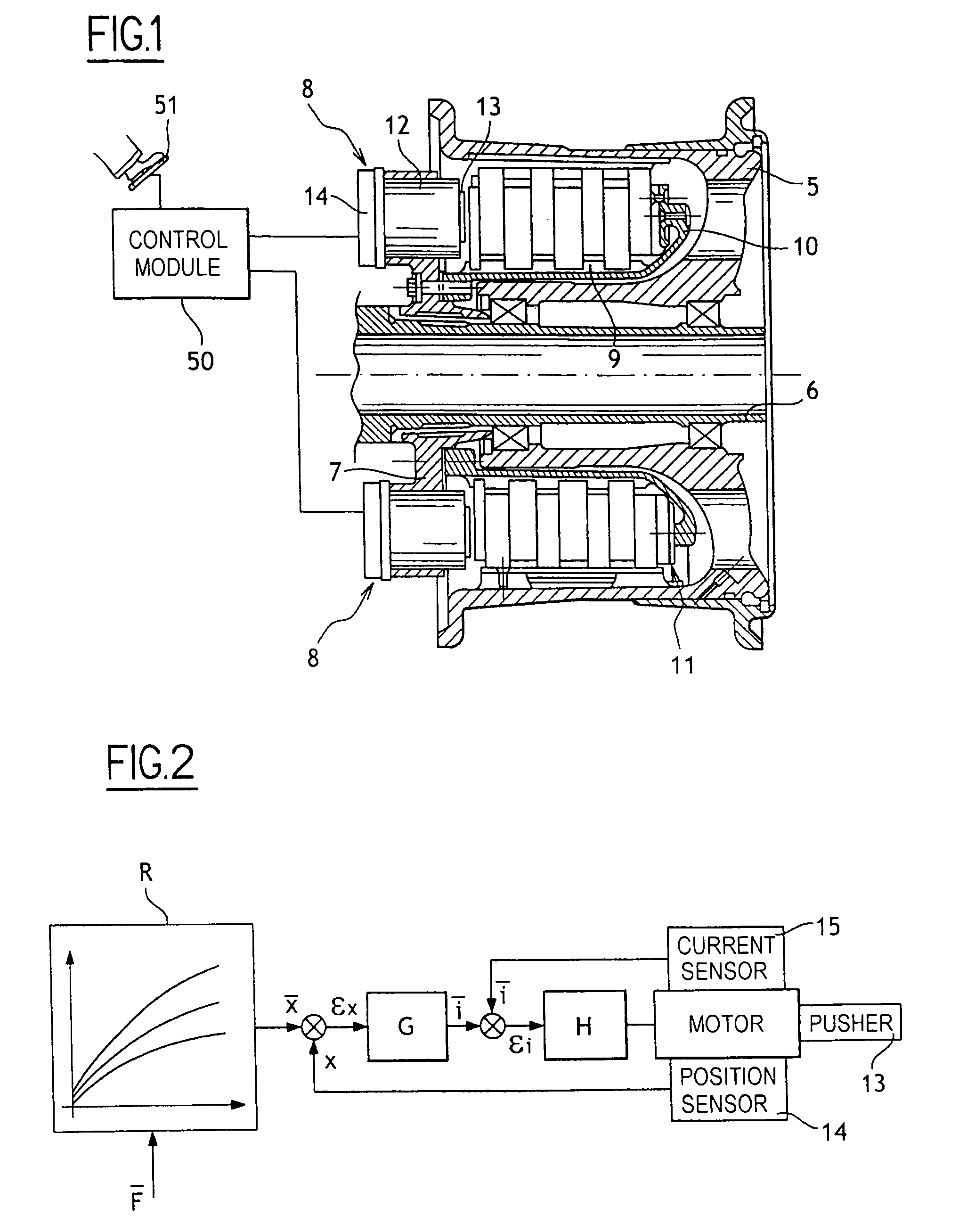
[0035]The method of the invention is described in detail herein in application to an aircraft that has some number of braked wheels, of the kind shown in FIG. 1. Each of the braked wheels comprises a rim 5 suitable for receiving a tire (not shown) and mounted to rotate on an axle 6 carried by one of the undercarriages of the aircraft. The axle 6 has mounted thereon a ring 7 carrying actuators 8. A torsion tube 9 is secured to the ring 7 and extends into the rim 5 and terminates with a backstop 10. The ring 7, and thus the torsion tube 9, are prevented from turning relative to the axis 6 by keying means (not shown).

[0036]Between the rest 10 and the actuators 8 there extends a stack of disks 11 made up of rotor disks that are constrained in rotation with the rim 5, and stator disks that are constrained in rotation with the torsion tube 9.

[0037]Each of the actuators 8 comprises a body 12 in which a pusher 13 is mounted facing the stack of disks 11 to move linearly under drive from an e...


PUM


Abstract

The invention relates to a method of servo-control in a vehicle braking system that includes at least one electric brake provided with at least one actuator comprising a pusher facing friction elements and driven by an electric motor to apply a force selectively against the friction elements in response to a braking setpoint, the method making use of a relationship for transforming a setpoint for the braking that is to be applied by the pusher into a setpoint for the position of the pusher. The method of the invention includes the step of adjusting a particular relationship by imposing pauses in the position of the pusher.

Description

[0001]This is a Continuation-in-Part of Application No. 11 / 134,361 filed May. 23, 2005. The entire disclosure(s) of the prior application(s), application number(s) 11 / 134,361 is hereby incorporated by reference.[0002]The invention relates to a method of servo-control in a braking system having electric brakes.BACKGROUND OF THE INVENTION[0003]Modern aircraft have braking systems including electric brakes provided with electromechanical actuators.[0004]Each actuator comprises a pusher facing a stack of disks and moved under drive from an electric motor to apply a braking force on the stack of disks in selective manner.[0005]Such brakes are generally under force control based on a braking setpoint.[0006]The invention applies more particularly to an actuator provided with a sensor for sensing pusher position, but not including a force sensor capable of measuring the force applied by the pusher against the stack of disks.[0007]Under such circumstances, in order to be able to servo-contro...

Claims


Application Information

Patent Timeline
Patent Type & Authority Patents(United States)
IPC IPC(8): G06F7/70G06F19/00B60T13/74F16D65/18
CPCB60T8/1703B60T13/741
Inventor THIBAULT, JULIEN
Owner SAFRAN LANDING SYSTEMS
Why Eureka
Try Eureka