Drill with a centering drill insert, and a method of using a drill with a centering drill insert, and the insert therefor

a drill and insert technology, applied in the field of cutting inserts, can solve the problems of poor drill-hole quality, hardly practicable in the manufacture of cutting inserts in such a way, and increase the tendency of the tool to dri

Active Publication Date: 2013-07-02
KENNAMETAL INC
View PDF14 Cites 10 Cited by
  • Summary
  • Abstract
  • Description
  • Claims
  • Application Information

AI Technical Summary

Benefits of technology

[0012]In at least one possible embodiment, the cutting insert includes an inner lip and an outer lip. These inner and outer lips form the sides of an angle, i.e. the cutting insert has an angular cutting edge. In the area of the vertex of the angle forming the cutting edge, a pimple-shaped protuberance is provided according to at least one possible embodiment. This protuberance additionally centers the cutting edge during the drilling operation. The protuberance has a very short length and essentially only covers the vertex of the angle formed by the inner and outer lips. Furthermore, the protuberance does not protrude very far from the cutting edge of the cutting insert. The protuberance serves in a way as a centering point for the cutting edge during the drilling operation. The essential cutting effort is still carried out by the inner lip on the one hand and the outer lip on the other hand, which are adjacent to the protuberance, while the protuberance, in addition to a cutting function, also has a centering function for the tool during the drilling operation. The centering function, in at least one possible embodiment, compensates for the drifting of the drill away from the center that occurs during drilling of a hole.
[0016]A symmetric structure of the entire cutting edge is desirable in at least one possible embodiment. This allows an easy exchange of the insert and the use in both a left-hand and a right-hand tool. Thus, the entire cutting edge may be arranged symmetrically around the protuberance. The length of the inner lip may be, in accordance with at least one embodiment, identical to the length of the outer lip. The same applies to the protuberance lips, if provided.
[0018]To make it possible to use the cutting insert in both left-hand and right-hand tools or to change the direction of rotation of the tool, a clearance may be arranged in the area of the flank allocated to the protuberance.
[0019]In at least one possible embodiment, it may be desirable—as mentioned above—to use a cutting tool with several cutting edges, designed as an indexable tip. The double function of the protuberance in an indexable tip may be advantageous. While the protuberance of the active cutting edge serves for the above-described improvement of the drilling behavior, the protuberance of an inactive cutting edge protrudes, with inserted indexable tip, into the corner hole which at least one possible embodiment, arranged between the insert bearing faces of the insert seat, thus preventing a jamming of chips in this corner hole. That means that the protuberance located in the corner hole serves as a filler for the corner hole.

Problems solved by technology

Due to the work tolerances inevitable in tool manufacture, it is, however, hardly possible in practice to manufacture a cutting insert in such a way that the above-mentioned unilateral drifting of the tool is completely excluded.
The use of several cutting inserts entails, furthermore, the problem that the tolerance faults, in the worst case, add up, resulting in an increased tendency to drifting of the tool.
Due to the antipenetration cutting force component, which is then effective, the drilling tool runs in an unstable manner during application, which will result in a poor drill-hole quality and an early failure of the tool.
This entails, however, an unfavorable chip shape.
Furthermore, it enlarges the engagement length of the cutting edge, which, in turn, leads to an undesired increase of the cutting forces and to an enlargement of the depth of the first cut.
However, this arrangement of the cutting edges results in an undesired chip shape, namely ribbon chips.
In some applications, a symmetric structure results in an unbalanced introduction of forces into the cutting insert during the cutting operation.
During a cutting operation, the forces exerted on the outer cutting insert are such that the drill may have a tendency to wander or drift off of center, thereby causing an inaccurately drilled hole, such as a drill that is not straight or has sections of differing diameter.

Method used


Image

  • Drill with a centering drill insert, and a method of using a drill with a centering drill insert, and the insert therefor
  • Drill with a centering drill insert, and a method of using a drill with a centering drill insert, and the insert therefor
  • Drill with a centering drill insert, and a method of using a drill with a centering drill insert, and the insert therefor

Examples


Embodiment Construction

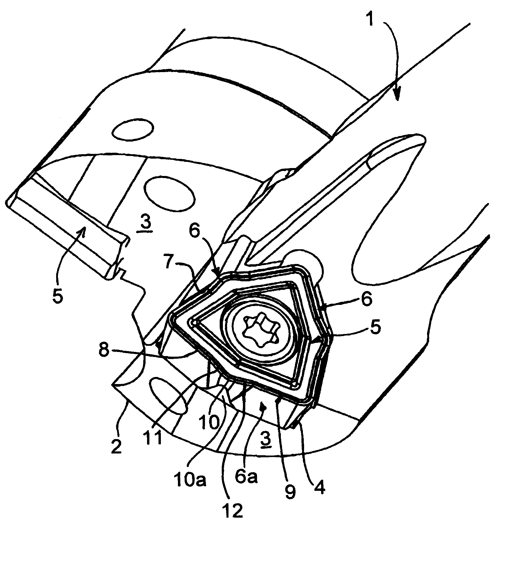
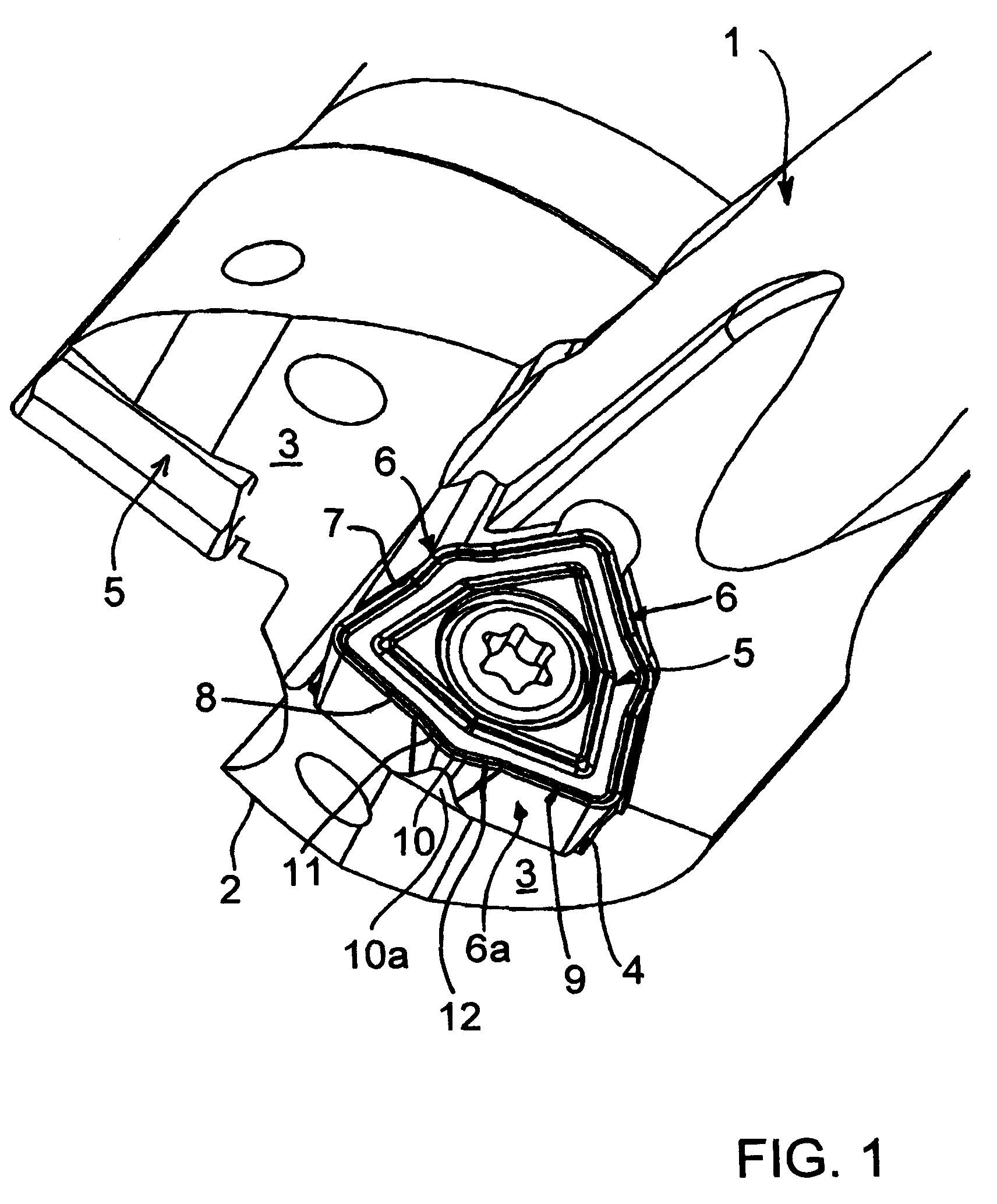
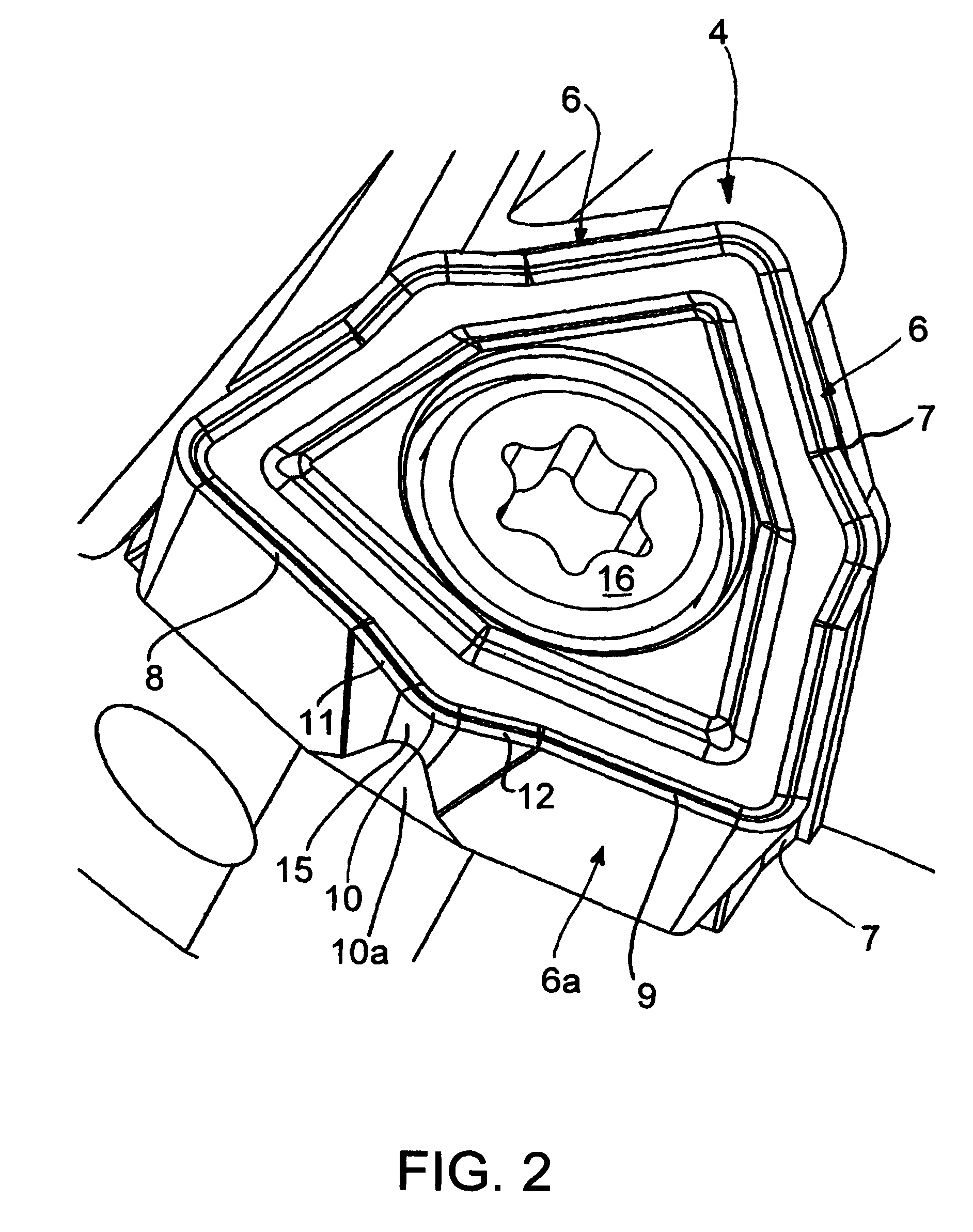
[0029]The drill 1 has a drilling point 2. The front face of this drilling point 2 includes two main flanks 3. Each main flank 3 is adjacent to an insert seat 4 for receiving a cutting insert 5 designed as an indexable tip. The cutting insert 5 shown in FIGS. 1 and 2 has an almost triangular outline. Each side of this triangular outline acts as a cutting edge 6. Adjacent to the cutting edges 6, there are side faces 6A, with each of which the cutting insert 5 abuts on an insert bearing face 7 of the insert seat 4.

[0030]The cutting edge 6 not oriented towards the insert bearing faces 7 forms the active cutting edge of the cutting insert 5. The active cutting-edge of the cutting insert 5 is subdivided into an inner lip 8 and an outer lip 9. The protuberance 10 is arranged between the inner lip 8 and the outer lip 9. A clearance 10A formed in the manner of a recess is provided on the side face 6A below the protuberance 10.

[0031]The flanks of the protuberance 10 are effective as protubera...


PUM

PropertyMeasurementUnit
angleaaaaaaaaaa
interior angleaaaaaaaaaa

Abstract

An insert includes a body portion and at least one cutting edge disposed on the periphery thereof. The cutting edge includes an inner lip and an outer lip disposed at an angle with respect to one another. A line extending along the inner lip intersects with a line extending along the outer lip at the vertex of the angle. The angular cutting edge further includes a protuberance disposed between, and connecting the inner and outer lips and projecting outwardly away from the body portion beyond the vertex of the angle defined by the intersection of the lines extending from the inner and outer lips. The protuberance having an inner lip connected to the inner lip of the cutting edge and an outer lip connected to the outer lip of the cutting edge to form smooth curvilinear transitions between the lips of the protuberance and the lips of the cutting edge.

Description

CONTINUING APPLICATION DATA[0001]This application is a Continuation-In-Part application of International Patent Application No. PCT / EP2007 / 001798, filed on Mar. 2, 2007, which claims priority from Federal Republic of Germany Patent Application No. DE 10 2006 010 856.6, filed on Mar. 9, 2006. International Patent Application No. PCT / EP2007 / 001798 was pending as of the filing date of this application. The United States was an elected state in International Patent Application No. PCT / EP2007 / 001798.BACKGROUND[0002]1. Technical Field[0003]The application relates to a cutting insert for a drill according to at least one possible embodiment disclosed herein. The application further relates to a cutting insert designed as a single or double-sided indexable tip. Such indexable tips have, for example, a triangular, tetragonal, such as a square, pentagonal or hexagonal outline. The edges located between the corners are formed as cutting edges. The indexable tip is arranged in the insert seat o...

Claims


Application Information

Patent Timeline
Patent Type & Authority Patents(United States)
IPC IPC(8): B23B51/02
CPCB23B27/141B23B51/048B23B2200/123B23B2200/125B23B2200/204Y10T408/9098Y10T407/235Y10T407/23Y10T408/03Y10T408/905Y10T408/455B23B2200/0419B23B51/00B23B27/14B23B51/04
Inventor MERGENTHALER, PETER KARLZEUG, BERTHOLD HEINRICHJAEGER, HORST MANFRED
Owner KENNAMETAL INC
Why Eureka
Try Eureka