
Piezo injector

A fuel injector, piezoelectric technology, used in fuel injection valves driven by fluid pressure, fuel injection devices, machines/engines, etc. Oiler degree of freedom, improvement and other issues

Inactive Publication Date: 2014-03-19
CONTINENTAL AUTOMOTIVE GMBH
View PDF5 Cites 4 Cited by
  • Summary
  • Abstract
  • Description
  • Claims
  • Application Information

AI Technical Summary

Problems solved by technology

Therein, an almost play-free coupling between the piezo actuator and the injector needle is required, which is however difficult to maintain due to thermally induced length changes in piezo injectors
The idle travel between the piezoelectric actuator and the injector needle is too small to completely close the injector needle
Too much idle travel between the piezo actuator and the injector needle leads to an increase in the actuation energy necessary to actuate the piezo injector
Attempts in the prior art to compensate for thermally induced length changes through suitable material selection and geometry lead to excessive manufacturing costs and significantly limit the structural possibilities when designing piezo injectors degrees of freedom on

Method used


Image

  • Piezo injector
  • Piezo injector

Examples


Embodiment Construction

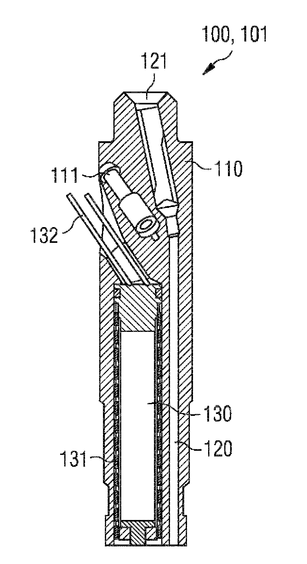
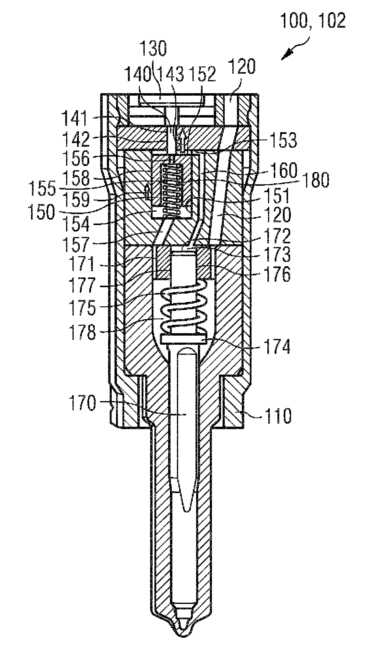
[0019] exist figure 1 with figure 2 A cross-sectional view of piezoelectric injector 100 is shown in . figure 1 The top half 101 of the piezo injector 100 is shown. figure 2 Bottom half 102 of piezo injector 100 is shown. The piezo injector 100 can be used to inject fuel in an internal combustion engine. For example, the piezo injector 100 can be used for injecting diesel in a common rail internal combustion engine.

[0020] The piezo injector 100 has an injector housing 110 . Injector housing 110 may consist of largely any material, since the thermal expansion properties of injector housing 110 are not significant. In particular, the injector housing 110 does not have to be made of low-expansion steel (Invar).

[0021] High-pressure bores 120 are arranged in injector housing 110 . Fuel under high pressure can be fed to the high-pressure opening via the high-pressure connection 121 . The high-pressure bore 120 extends in the longitudinal direction through the injecto...


PUM


Abstract

A piezo injector (100) comprises an actuator chamber (131), in which a piezo actuator (130) is arranged, comprises a control piston bore (151), in which is arranged a control piston (150) which has a first end side (152) facing toward the piezo actuator (130), wherein a portion of the control piston bore (151) delimited by the first end side (152) forms a first control chamber (153) and a portion of the control piston bore (151) situated opposite the first control chamber (153) forms a spring chamber (154), and wherein the control piston (150) is arranged between the first control chamber (153) and the spring chamber (154), comprises a nozzle needle (170) having a second end side (172), wherein the nozzle needle (170) guides a nozzle needle sleeve (171), wherein the nozzle needle sleeve (171) and the second end side (172) delimit a second control chamber (173), comprises a connecting bore (160) between the first control chamber (153) and the second control chamber (173), and comprises a leakage pin (140), which is arranged between the piezo actuator (130) and the first end side (152) in a leakage pin bore (141).

Description

technical field [0001] The invention relates to a piezoelectric fuel injector according to claim 1 . Background technique [0002] Internal combustion engines with direct fuel injection are known. For direct fuel injection, piezo injectors are used whose injector needles are actuated by means of piezo actuators. It is required here to achieve an almost play-free coupling between the piezo actuator and the injector needle, which is however difficult to maintain due to thermally induced length changes in piezo injectors. The idle travel between the piezo actuator and the injector needle is too small to close the injector needle completely. Too much free play between the piezo actuator and the injector needle leads to an increase in the actuation energy required for actuating the piezo injector. Attempts in the prior art to compensate for thermally induced length changes through suitable material selection and geometry lead to excessive manufacturing costs and significantly ...

Claims


Application Information

Patent Timeline
IPC IPC(8): F02M51/06F02M61/16
CPCF02M61/167F02M2200/28F02M2200/703F02M2547/001F02M51/0603
Inventor W.许尔茨
Owner CONTINENTAL AUTOMOTIVE GMBH
Learn More