LED tube lamp

a technology of led tube lamps and end caps, which is applied in the direction of semiconductor devices for light sources, coupling device connections, lighting and heating apparatus, etc., can solve the problems of reducing the luminous efficiency, and reducing the overall lighting or luminous efficiency of conventional led tube lamps. , to achieve the effect of improving the production efficiency of led tube lamps, reducing the risk of glass lamp tubes breaking, and widening the surfa

Active Publication Date: 2016-10-06
JIAXING SUPER LIGHTING ELECTRIC APPLIANCE
View PDF4 Cites 32 Cited by
  • Summary
  • Abstract
  • Description
  • Claims
  • Application Information

AI Technical Summary

Benefits of technology

[0074]Another benefit of the LED tube lamp fabricated in accordance with the embodiment of present invention is that actual curing of the hot melt adhesive by the energized induction coil is performed more uniformly and done more precisely, thus the bonding of the end cap, the magnetic metal member, and the lamp tube are more secure and lasting.
[0075]Another benefit of the LED tube lamp fabricated in accordance with the embodiments of present invention is that due to the difference in height between the outer surface of the rear end region and the outer surface of the main region of the lamp tube and the presence and location of the magnetic metal member in relation to the transition region and the main region of the lamp tube, overflow or spillover of the hot melt adhesive to the main region of the lamp tube can be totally avoided, forsaking or avoiding having to perform manual adhesive wipe off or clean off, thus improving LED tube lamp production efficiency.
[0076]Another benefit of the LED tube lamp fabricated in accordance with the embodiments of present invention is that due to the substantial aligning of the center line of the end cap and the center line of the glass lamp tube, the outer diameter of the end cap and of lamp tube are substantially equal, so that the entire LED tube lamp (assembly) appears to have an integrated planar flat surface. As a result, during shipping or transport of the LED tube lamp, the shipping packaging...

Problems solved by technology

Because this type of aluminum alloy housing is a conductive material, thus is prone to result in electrical shock accidents to users.
In addition, the light transmittance of the plastic cover or the plastic tube diminish over time due to aging, thereby reducing the overall lighting or luminous efficiency of the conventional LED tube lamp.
Furthermore, grainy visual appearance and other derived problems reduce the luminous efficiency, thereby reducing the overall effectiveness of the use of LED tube lamp.
With respect to each LED chip, due to its intrinsic illumination property, if there was no any sufficient further optical processing, the entire tube light will exhibit grainy or non-uniform illumination effect; as a result, grainy effect is produced to the viewer or user, thereby negatively affect visual aesthetics thereof.
In other words, the overall illumination distribution uniformity of the light outputted by the LED light sources without having additional optical processing techniques or structures for modifying the illumination path and uniformity would not be sufficient enough to satisfy the quality and aesthetics requirements of average consumers.
During shipping or transport of the LED tube lamp, the shipping packaging support/bracket only makes direct contact with the end caps, thus rendering the end caps as being the only load/stress points, which can easily lead to breakage at the transition region with the glass lens.
But this type of conventional tube lamp configured with the plastic end caps requires a tedious process for performing adhesive bonding attachment because the adhesive bonding process requires a significant amount of time to perform, leading to production bottleneck or difficulties.
In addition, manual operation or labor are required to perform such adhesive bonding process, thus would be difficult for manufactu...

Method used


Image

  • LED tube lamp
  • LED tube lamp
  • LED tube lamp

Examples


second embodiment

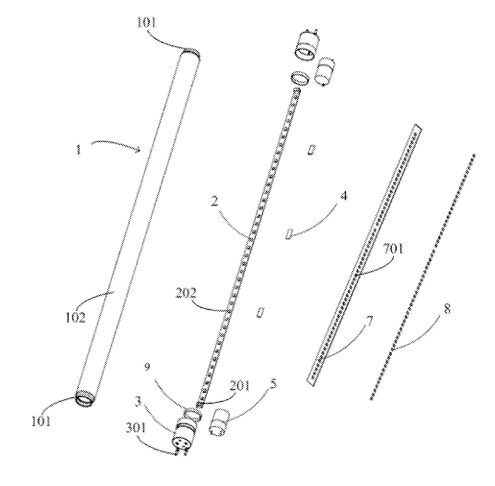
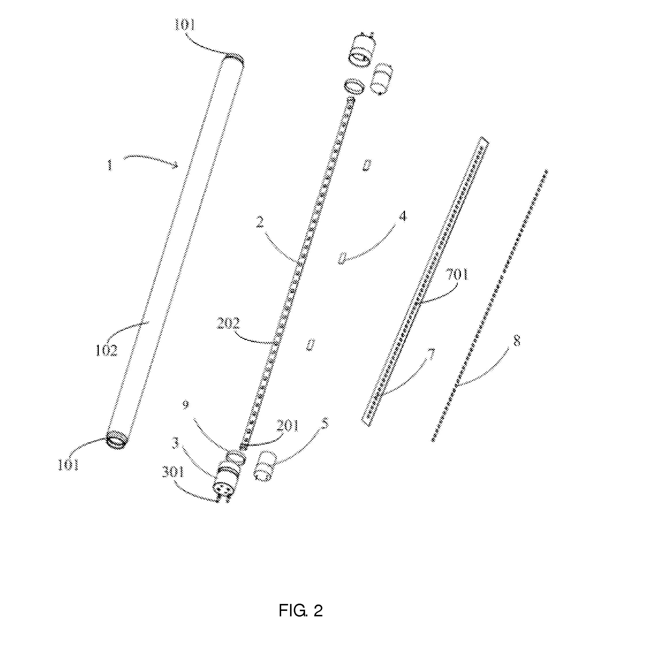
[0115]The thermal conductive ring 303 can be made of various heat conducting materials, the thermal conductive ring 303 of the present embodiment is a metal sheet, such as aluminum alloy. The second tubular part 302b is sleeved with the thermal conductive ring 303 being tubular or ring shaped. The electrically insulating tubular part 302 may be made of electrically insulating material, but would have low thermal conductivity so as to prevent the heat conduction to reach the power supply components located inside the end cap 3, which then negatively affect performance of the power supply components. In this embodiment, the electrically insulating tubular part 302 is a plastic tube. In other embodiments, the thermal conductive ring 303 may also be formed by a plurality of metal plates arranged along a plurality of second tubular part 302b in either circumferentially-spaced or not circumferentially-spaced arrangement. In other embodiments, the end cap may take on or have other structur...

first embodiment

[0125]To improve the illumination efficiency of the LED tube lamp, the lamp tube 1 has been modified according to present invention by having a diffusion film layer 13 coated and bonded to the inner wall thereof as shown in FIG. 12, so that the light outputted or emitted from the LED light sources 202 is transmitted through the diffusion film layer 13 and then through the lamp tube 1. The diffusion film layer 13 allows for improved illumination distribution uniformity of the light outputted by the LED light sources 202. The diffusion film layer 13 can be coated onto different locations, such as onto the inner wall or outer wall of the lamp tube 1 or onto the diffusion coating layer (not shown) at the surface of each LED light source 202, or coated onto a separate membrane cover covering the LED light source 202. The diffusion film layer 13 in the illustrated embodiment of FIG. 12 is a diffusion film that is not in contact with the LED light source 202 (but covering above or over to ...


PUM


Abstract

An end cap for LED tube lamp along with the LED tube lamp adopting thereof is disclosed. LED tube lamp includes a lamp tube. One end of the lamp tube is attached to the end cap; a LED light bar is disposed inside the lamp tube. The end cap includes an insulating tubular part, sleeved with the end of the lamp tube and a magnetic object disposed between an inner circumferential surface of the insulating tubular part and the end of the lamp tube. The magnetic object being of a magnetic metal member and the lamp tube are adhesively bonded by a hot melt adhesive. An inner circumferential surface of the magnetic metal member can be fully covered by the hot melt adhesive. Magnetic metal member can be in the structure of a circular or oval ring, with at least one opening, and has indentation structure on a surface thereof.

Description

FIELD OF THE INVENTION[0001]The present invention relates to illumination device, and more particularly to an end cap for an LED tube lamp adapted for use together with an LED tube lamp.BACKGROUND OF THE INVENTION[0002]Today LED lighting technology is rapidly replacing traditional incandescent and fluorescent lights. Even in the tube lamp applications, instead of being filled with inert gas and mercury as found in fluorescent tube lamps, the LED tube lamps are mercury-free. Thus, it is no surprised that LED tube lamps are becoming highly desired illumination option among different available lighting systems used in homes and workplace, which used to be dominated by traditional lighting options such as compact fluorescent light bulbs (CFLs) and fluorescent tube lamps. Benefits of the LED tube lamps include improved durability and longevity, and far less energy consumption, therefore, when taking into of all factors, they would be considered as cost effective lighting option.[0003]The...

Claims


Application Information

Patent Timeline
IPC IPC(8): F21K99/00
CPCF21Y2103/003F21K9/17F21K9/27F21K9/90F21Y2103/10F21Y2115/10H01R13/6205
Inventor JIANG, TAOJIANG, WEN-JANGCHEN, SHAU-LIANGYANG, XIAO-SU
Owner JIAXING SUPER LIGHTING ELECTRIC APPLIANCE
Why Eureka
Try Eureka