Rotary column separator

A separator and rotary tower technology, applied in the field of sewage treatment devices, can solve the problems of short sewage flow path, complex structure and operation, low filtration efficiency, etc., and achieve the effect of improving filtration efficiency.

Inactive Publication Date: 2008-12-03
孙成义
View PDF7 Cites 13 Cited by
  • Summary
  • Abstract
  • Description
  • Claims
  • Application Information

AI Technical Summary

Problems solved by technology

[0002] With the continuous acceleration of the industrialization process and the continuous improvement of living standards, the treatment of industrial sewage and domestic sewage has become an urgent problem to be solved. In the application number 92210671.1, a slag-liquid separation vacuum filter device is disclosed. The lower end of the filter is connected to the vacuum water tank through a connector. The filter cloth is arranged on the sieve plate in the filter. When working, the material liquid is input into the filter. The filter is not a vacuum environment, and the filtered water is sucked into the filter. In the vacuum water tank, when the vacuum water tank is full, another vacuum water tank is opened, and the two vacuum water tanks work in a cycle. This structure is complicated to operate, and the sewage flows in a straight line in the filter. The flow route of the sewage is short and the filtration efficiency is not high. , which is the shortcoming of existing technology

Method used


Image

  • Rotary column separator
  • Rotary column separator
  • Rotary column separator

Examples


Embodiment Construction

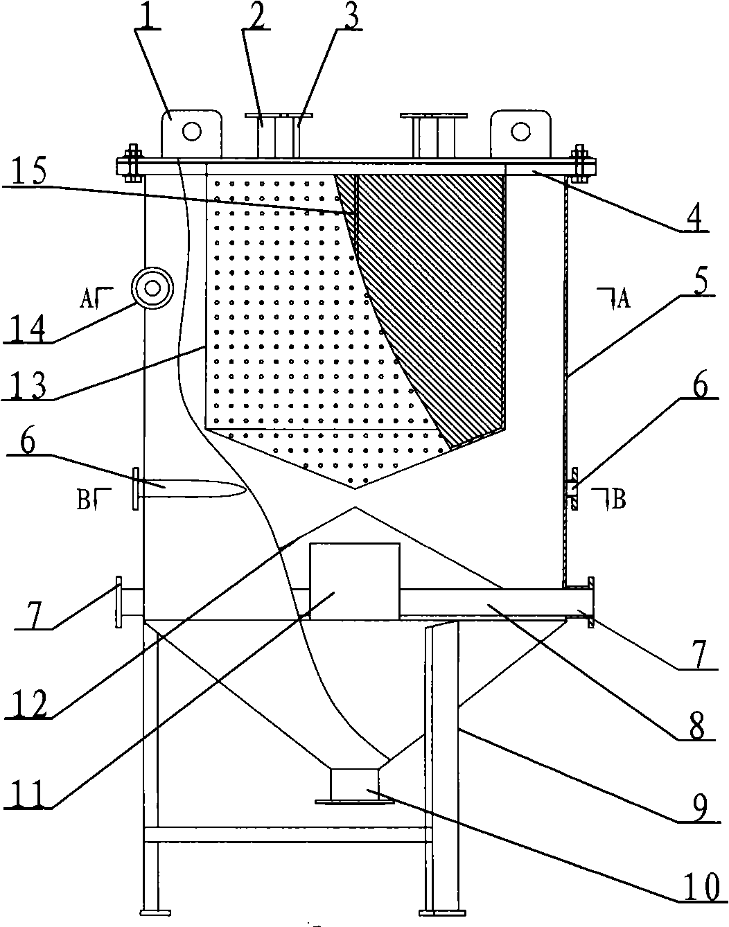
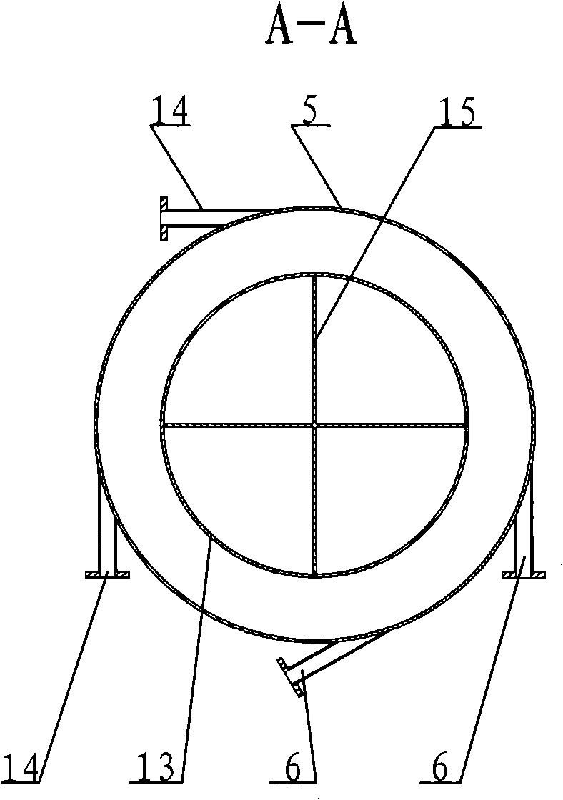
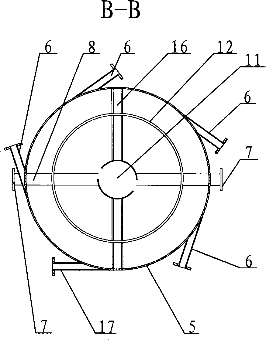
[0010] In order to clearly illustrate the technical features of the solution, the solution will be described below through a specific implementation mode combined with the accompanying drawings.

[0011] As can be seen from the accompanying drawings, the rotary column separator of this program includes a support 9 and a liquid storage cylinder 5 with a loam cake 4 on the support 9, and a feed port 17 is arranged on the side wall of the liquid storage cylinder 5. The bottom of the liquid cylinder 5 has a discharge port 10. The liquid storage cylinder 5 described in this program is a cylinder with a tapered bottom. The liquid storage cylinder 5 and the upper cover 4 form a closed pressure vessel. 17 is the feed port 17 that enters tangentially on the side wall of the liquid storage cylinder 5. On the side wall of the liquid storage cylinder 5, there are also the water inlet 6 that enters tangentially, the water outlet 14 that enters tangentially and the water outlet 14 that enter...


PUM


Abstract

The invention provides a turret separator, comprising a bracket and a liquid storage cylinder which is arranged on the bracket and is provided with an upper cover. The bottom of the liquid storage cylinder is provided with a conical cylinder; the lower part of the liquid storage cylinder is provided with a discharge port; the liquid storage cylinder and the upper cover form a hermetic pressure vessel; a filter cartridge with a conical bottom is fixedly connected with the upper cover in the liquid storage cylinder; the side wall of the filter cartridge is provided with a filtration fabric; an inner cavity of the filter cartridge is provided with at least one chamber; the chamber is provided with an exhaust pipe and a filtration fabric backwash pipe which are correspondingly connected with an exhaust port and a filtration fabric backwash port on the upper cover corresponding to the exhaust pipe and the filtration fabric backwash pipe of each chamber; the side wall of the liquid storage cylinder is provided with a tangential ingoing feeding port, a tangential ingoing water inlet, a tangential ingoing water outlet and a vertical ingoing drainage port; a feed distributing cone is arranged above a cone in the liquid storage cylinder with a diameter less than that of the liquid storage cylinder, and is opposite to the cone on the bottom of the liquid storage cylinder; and a pumping barrel which is connected with the drainage port through a connecting pipe is arranged under the feed distributing cone.

Description

Technical field: [0001] The invention relates to a sewage treatment device, in particular to a rotary tower separator. Background technique: [0002] With the continuous acceleration of the industrialization process and the continuous improvement of living standards, the treatment of industrial sewage and domestic sewage has become an urgent problem to be solved. In the application number 92210671.1, a slag-liquid separation vacuum filter device is disclosed. The lower end of the filter is connected to the vacuum water tank through a connector. The filter cloth is arranged on the sieve plate in the filter. When working, the material liquid is input into the filter. The filter is not a vacuum environment, and the filtered water is sucked into the filter. In the vacuum water tank, when the vacuum water tank is full, another vacuum water tank is opened, and the two vacuum water tanks work in a cycle. This structure is complicated to operate, and the sewage flows in a straight l...

Claims


Application Information

Patent Timeline
Patent Type & Authority Applications(China)
IPC IPC(8): C02F1/38
Inventor 孙成义孙泽海张宝山
Owner 孙成义
Why Eureka
Try Eureka