Combined grooved pulley mechanism

A combination of groove and sheave technology, applied in mechanical equipment, belts/chains/gears, transmission devices, etc., can solve the problems of large space occupation, large rigid impact, and heavy weight

Inactive Publication Date: 2008-12-10
ZHEJIANG UNIV OF TECH
View PDF0 Cites 8 Cited by
  • Summary
  • Abstract
  • Description
  • Claims
  • Application Information

AI Technical Summary

Problems solved by technology

[0003] This invention solves the shortcomings of the existing sheave mechanism, such as large rigid impact, lar...

Method used


Image

  • Combined grooved pulley mechanism
  • Combined grooved pulley mechanism
  • Combined grooved pulley mechanism

Examples


Embodiment Construction

[0015] Referring to the attached picture:

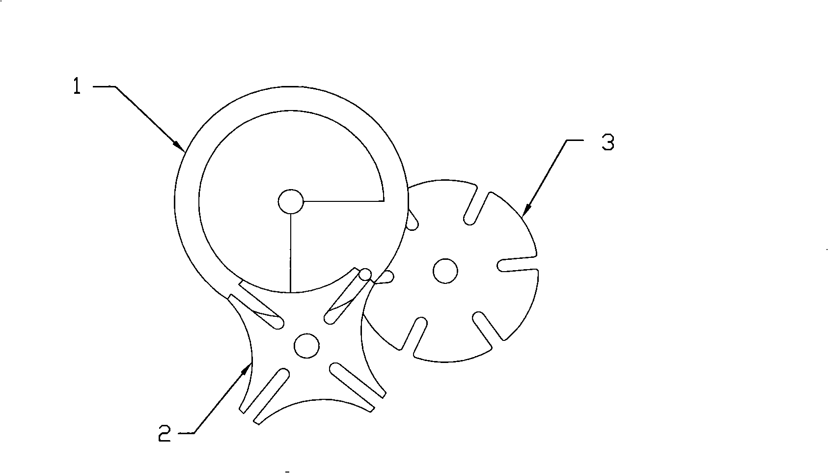
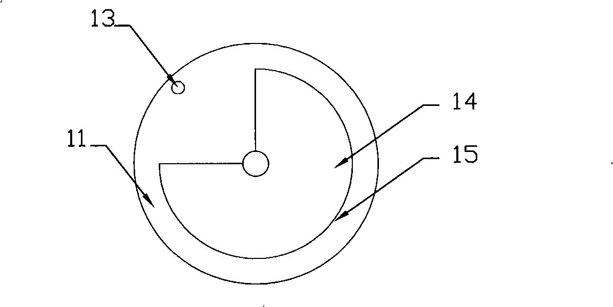
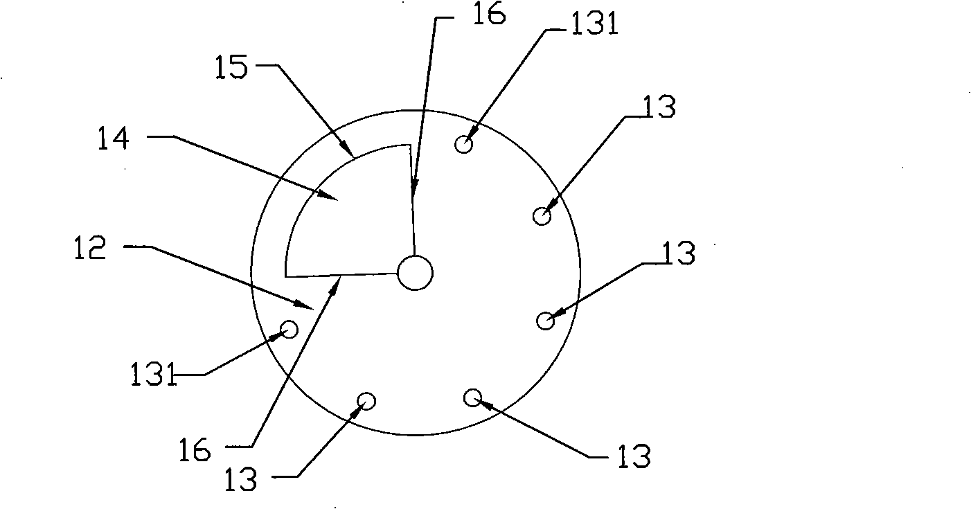
[0016] Realize the combined sheave mechanism of the present invention, including a driving dial 1 and a first sheave 2, the circular pins 13 for transmitting power and the locking arcs for locking the sheave are evenly distributed on the front face 11 of the dial Platform 14; the distance from the center of circle of the round pin 13 to the center of the dial is greater than or equal to the sum of the radius of the round pin 13 and the radius of the locking arc protrusion 14; the outer edge 15 of the locking arc protrusion It has a circular profile, and the opening angle of the locking arc protrusion 14 is the inter-groove angle formed by the centerlines of two adjacent straight grooves on the sheave 2 plus 180 degrees. Straight grooves 21 are evenly distributed on the first sheave 2, and the end of the straight grooves 21 is a semicircular arc 23 with the groove width as the diameter. Cooperate; the distribution between the two str...


PUM


Abstract

The invention relates to a combined sheave mechanism, comprising a driving plate and two driven sheave wheels. Both the front side and the back side of the driving plate are provided with a round pin which transmits the power and a locking arc boss. The front side and the back side of the driving plate drive a driven sheave wheel respectively to rotate; the locking arc bosses of the front side and the back side are opposite in phase. The invention is characterized in compact structure and small weight.

Description

1. Technical field [0001] The invention relates to a combined sheave mechanism 2. Background technology [0002] The sheave mechanism consists of a driving dial with round pins, a driven sheave with straight grooves and a frame. The active dial rotates continuously. When the round pin does not enter the straight groove, the sheave stops because the locking arc on it is locked by the locking arc protrusion of the dial; when the round pin starts to enter the straight groove, the locking The arc is disengaged from the locking arc protrusion, and the sheave rotates under the drive of the round pin; when the round pin starts to break away from the straight groove, the sheave stops because the locking arc is locked, thereby realizing the one-way rotation of the driven sheave. Turn intermittently. The disadvantage of this mechanism is: the sheave has a large rigid impact at the beginning and end of the movement; when it is necessary to convert the continuous rotation of the dial ...

Claims


Application Information

Patent Timeline
IPC IPC(8): F16H27/06
Inventor 顾张丽
Owner ZHEJIANG UNIV OF TECH
Why Eureka
Try Eureka