Supercharge Your Innovation With Domain-Expert AI Agents!

Movable contact element and switch using the same

A technology of moving contacts and contact bodies, applied in the direction of electric switches, electronic switches, electrical components, etc., which can solve the problems of increased number of parts, high cost of movable contact body 102 and switch 150, complex structure of switch 150, etc.

Inactive Publication Date: 2011-07-20
PANASONIC CORP
View PDF6 Cites 4 Cited by
  • Summary
  • Abstract
  • Description
  • Claims
  • Application Information

AI Technical Summary

Problems solved by technology

Therefore, the number of parts constituting the switch 150 increases, and the structure of the switch 150 becomes complicated.
As a result, there is a problem that the cost of the movable contact body 102 and the switch 150 is high.

Method used


Image

  • Movable contact element and switch using the same
  • Movable contact element and switch using the same
  • Movable contact element and switch using the same

Examples


Embodiment approach 1

[0040] Below, use figure 1 ~ Fig. 8, Embodiment 1 of the present invention will be described.

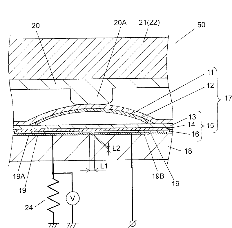
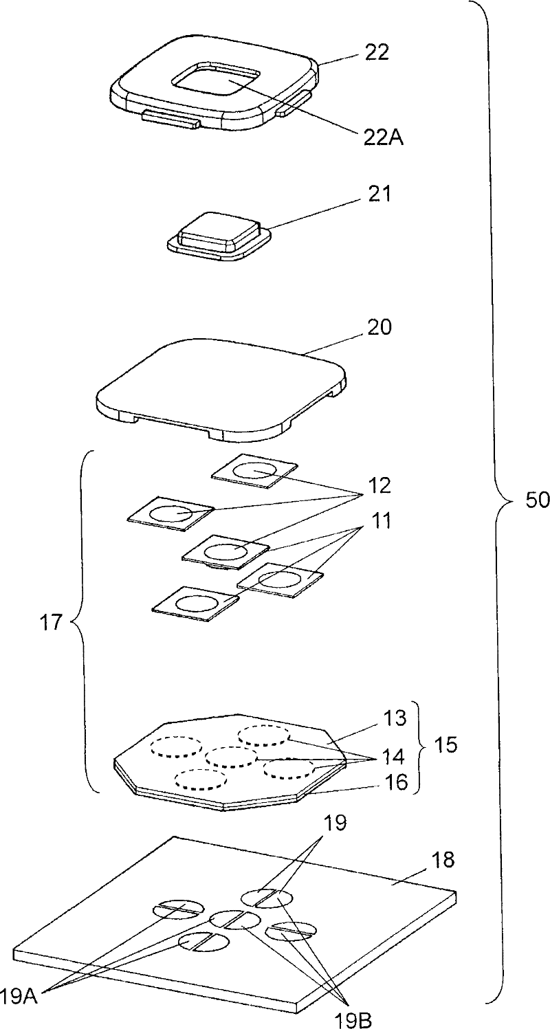
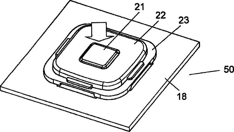
[0041] figure 1 It is a sectional view of the switch 50 according to Embodiment 1 of the present invention. figure 2 It is an exploded perspective view of the switch 50 . Figure 3A and Figure 3B is a perspective view of the switch 50 . Figure 4 is a cross-sectional view of a pressure-sensitive conductive plate 15 (hereinafter referred to as a sheet 15 ) employed in the switch 50 . Figure 5 It is a cross-sectional view when the switch 50 is pressed. Figure 6 is a characteristic diagram of the switch 50. Figure 7A It is a plan view of the display screen 30 of an electronic device (not shown) equipped with the switch 50 . Figure 7B It is a plan view of the display screen 30 of another mode of the electronic device equipped with the switch 50 . Figure 8A is a plan view of the fixed contact 19 used in the switch 50 . Figure 8B It is a plan view of another fixed conta...

Embodiment approach 2

[0071] Embodiment 2 of the present invention will be described below using the drawings. It should be noted that the same reference numerals are assigned to the same configuration as that of Embodiment 1, and detailed description thereof will be omitted.

[0072] Figure 9 It is a sectional view of switch 50A according to Embodiment 2 of the present invention. Figure 10 It is a plan view of the fixed contact 29 used in the switch 50A. Figure 11 is a characteristic diagram of switch 50A.

[0073] Such as Figure 9 and Figure 10 As shown, in the switch 50A, the movable contact 12 is pasted on the lower surface of the cover plate 11 . In addition, in the switch 50A, the cover plate 11 is pasted on the upper surface of the pressure-sensitive conductive plate 15 . These structures have the same structure as that of the first embodiment. In addition, in movable contact body 17A and switch 50A according to Embodiment 2, the outer periphery of pressure-sensitive conductive l...


PUM


Abstract

A movable contact element includes a cover sheet to which a movable contact having a dome shape is bonded and which is stacked on a top surface of a pressure sensitive conductive sheet. The movable contact element is bonded to a top surface of a substrate having a fixed contact formed thereon, thereby forming a switch. Through the construction, it is possible to obtain the movable contact element, which has a simple construction and can perform various operations, and the switch using the same.

Description

technical field [0001] The present invention relates to a movable contact body mainly used in the operation of various electronic devices and a switch using the movable contact body. Background technique [0002] In recent years, the high functionality and diversification of various electronic devices such as mobile phones and car navigation systems are progressing. With the evolution of electronic equipment, there is a demand for movable contacts and switches used for the operation of these electronic equipment, which are inexpensive and can perform various operations. [0003] use Figure 15 , to describe such a conventional movable contact body and a switch using the same. [0004] Figure 15 is a cross-sectional view of a conventional switch 150 . exist Figure 15 Among them, the switch 150 has a movable contact body 104 , a substrate 105 and a fixed contact 106 . The movable contact body 104 has a cover plate 101 and a movable contact 102 . The cover plate 101 is be...

Claims


Application Information

Patent Timeline
Patent Type & Authority Patents(China)
IPC IPC(8): H03K17/96H01H13/00H01H13/12
Inventor 吉原聪山本保泽田昌树
Owner PANASONIC CORP
Features
  • R&D
  • Intellectual Property
  • Life Sciences
  • Materials
  • Tech Scout
  • Unparalleled Data Quality
  • Higher Quality Content
  • 60% Fewer Hallucinations
Learn More