Alternation type receiving module

A receiving module and alternating technology, applied in the field of alternating receiving modules, can solve the problems of normal operation and use, users unable to open the device, etc.

Inactive Publication Date: 2008-12-10
翁酩富
View PDF0 Cites 2 Cited by
  • Summary
  • Abstract
  • Description
  • Claims
  • Application Information

AI Technical Summary

Problems solved by technology

However, although the above-mentioned conventional electronic remote control switch module is convenient, once the receiving host breaks down, it cannot be operated normally. In other words, the user cannot turn on the related device.
Therefore existing electronic remote control switch still has shortcoming in use and needs to be improved

Method used


Image

  • Alternation type receiving module
  • Alternation type receiving module
  • Alternation type receiving module

Examples


Embodiment Construction

[0021] In order to describe the structure, features and achieved effects of the present invention in detail, the following preferred embodiments are described below with accompanying drawings.

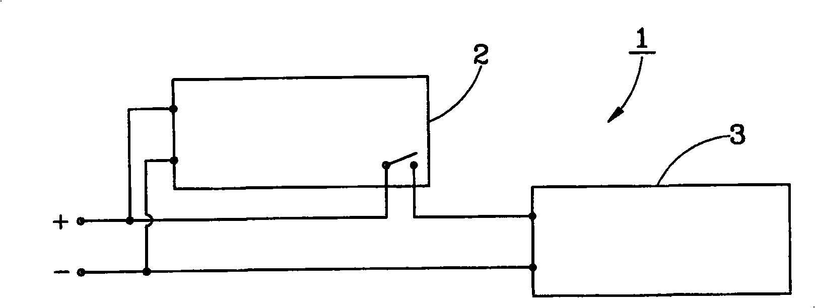
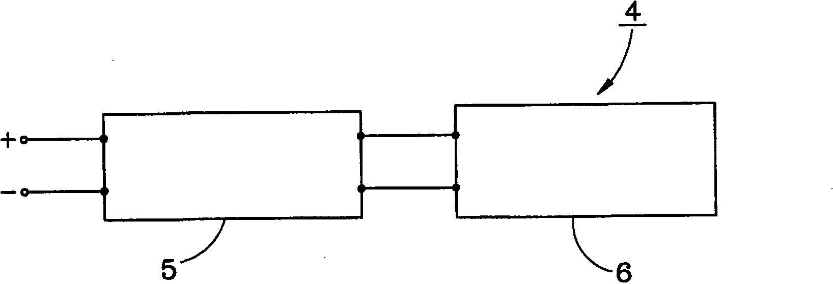
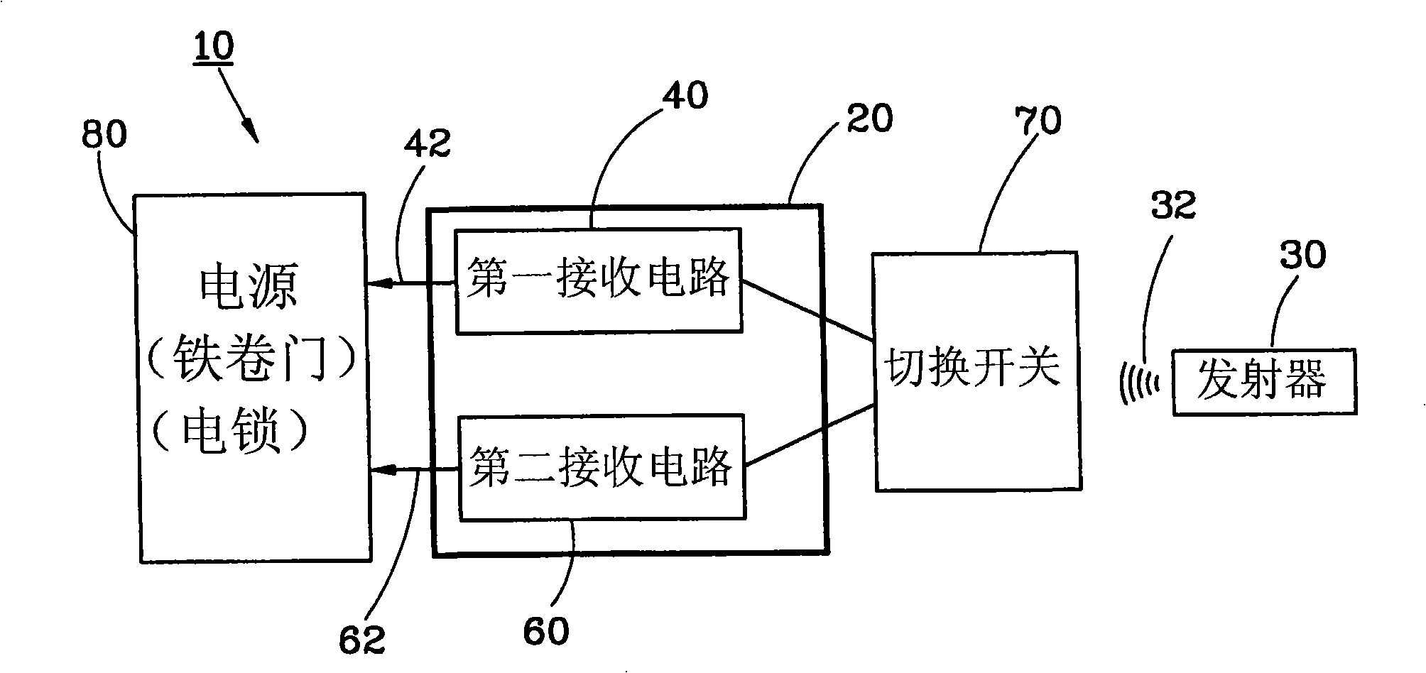
[0022] first as image 3 As shown, the alternate receiving module 10 provided by the first preferred embodiment of the present invention includes a main chassis 20, a transmitter 30, a first receiving circuit 40, a second receiving circuit 60 and a switch 70 .

[0023] The main box 20 is installed indoors for installing the first receiving circuit 40 and the second receiving circuit 60 , and providing power sources required by the first receiving circuit 40 , the second receiving circuit 60 and other related devices.

[0024] The transmitter 30 wirelessly sends a trigger signal 32 to the first receiving circuit 40 and the second receiving circuit 60 .

[0025] Such as image 3 As shown in FIG. 4 , the first receiving circuit 40 is arranged in the main box 20 , and when the first rec...


PUM


Abstract

The invention relates to an alternative type receiving module, including a host computer case; a first receiving circuit arranged in the host computer case, for transmitting a first control signal when the first receiving circuit receives a trigger signal of a transmitter, for driving the load device; a second receiving circuit arranged in the host computer case, connected with the first receiving circuit in parallel, for transmitting a second control signal when the second receiving circuit receives the trigger signal, for driving the load device; a diverter switch electrically connected with the first receiving circuit and the second receiving circuit, for switching between the first receiving circuit and the second circuit for the users. According to the invention, when one receiving circuit goes wrong, the other receiving circuit also can normally drives the electrolock or the electrical roller door.

Description

technical field [0001] The invention relates to an electronic switch, in particular to an alternate receiving module. Background technique [0002] The electronic remote control switch module is widely used. The general electronic remote control switch module is unlocked by infrared remote control. The user must use a specific frequency remote control to open a specific device to achieve the purpose of ensuring home safety. [0003] Such as figure 1 Shown is a system structure diagram of a conventional electronic remote control switch module. When the receiving host 2 of the electronic remote control switch module 1 receives the trigger signal from the correct remote controller, the receiving host 2 will send a control signal to drive the load device 3 from the latch state to the open state. Another example figure 2 As shown, it is also a system structure diagram of a conventional electronic remote control switch module. The difference is that the receiving host 5 of the...

Claims


Application Information

Patent Timeline
Patent Type & Authority Applications(China)
IPC IPC(8): H03K17/94
Inventor 翁酩富
Owner 翁酩富
Why Eureka
Try Eureka