Wheel bearing device, and its manufacturing method

A technology of a bearing device and a manufacturing method, applied in the directions of axles, wheels, ball bearings, etc., can solve the problems of short life, increased deformation of the inner ring, and redundant space.

Active Publication Date: 2008-12-10
NTN CORP
View PDF1 Cites 9 Cited by
  • Summary
  • Abstract
  • Description
  • Claims
  • Application Information

AI Technical Summary

Problems solved by technology

If the axial length of the inner ring step portion 36 is increased in this way, the inner ring step portion 36 tends to be located on a straight line constituting the contact angle of the rolling elements, thereby causing deformation of the inner ring due to the load during operation. Increased, short-lived likelihood
In addition, if the axial length of the inner ring step portion 36 is increased, the fitting length (area) of the inner ring 30 and the hub wheel 29 is reduced only by the increased amount, which may cause inner ring creep. , the possibility of reduced bearing life
These problems can be avoided if the overall width of the inner ring is increased, however, it is necessary to have extra space in the axial direction
[0008] (3) In addition, since the plastically deformed portion 29b of the hub wheel 29 is relatively large, the pressing punch interferes with the inner ring 30 during the swing pressing, making processing difficult.

Method used


Image

  • Wheel bearing device, and its manufacturing method
  • Wheel bearing device, and its manufacturing method
  • Wheel bearing device, and its manufacturing method

Examples


Embodiment Construction

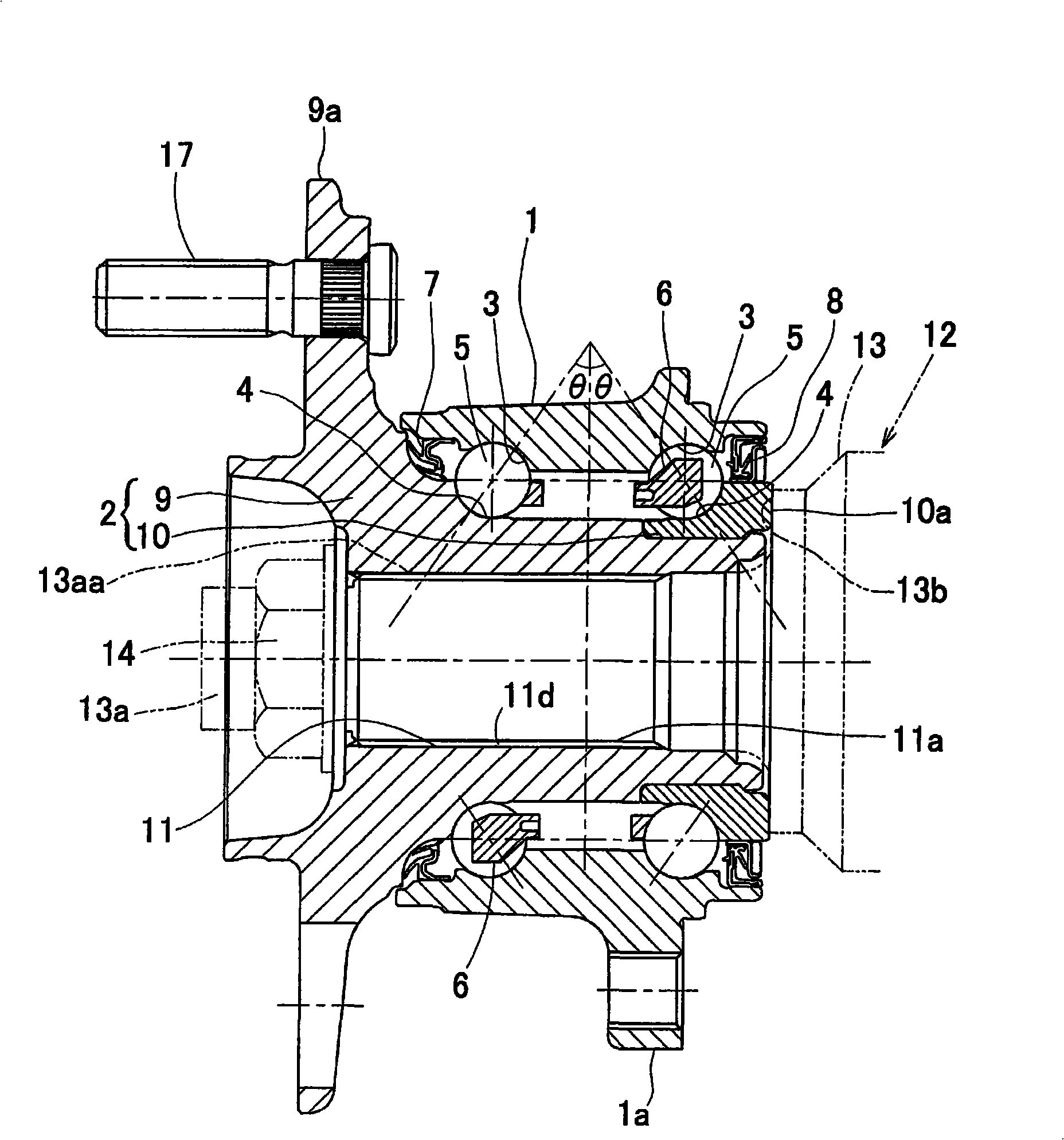
[0055] according to figure 1 ~ Fig. 3, the first embodiment of the present invention will be described. This embodiment is a third-generation inner ring rotation type, and is suitable for a wheel bearing device for supporting a drive wheel. In addition, in this specification, the side closer to the outer side in the vehicle width direction of the vehicle when mounted on the vehicle is referred to as the outer side, and the side closer to the middle portion of the vehicle is referred to as the inner side.

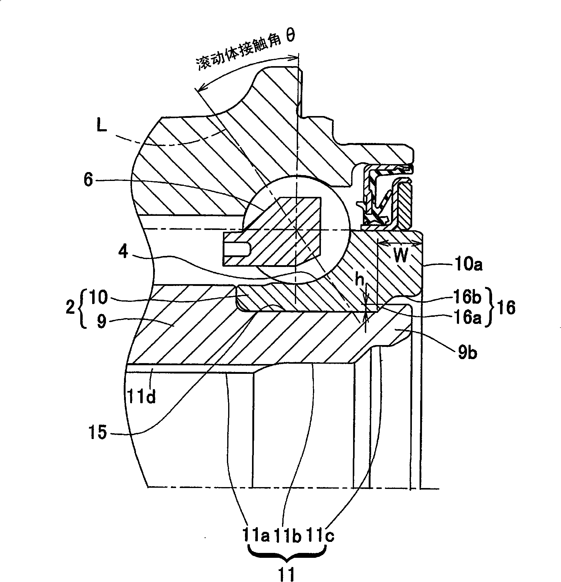
[0056] The bearing device for the wheel consists of an outer member 1 formed with a plurality of rows of raceway surfaces 3 on the inner periphery; an inner member 2 formed with a raceway surface 4 facing each of the raceway surfaces 3; and interposed between the outer member 1. It is composed of multiple rows of ball-shaped rolling elements 5 between the raceway surfaces 3 and 4 of the inner member 2 . This wheel bearing device is a multi-row outward thrust angular contac...


PUM


Abstract

A bearing device for a wheel, in which coming out of an inner ring in the process of assembling the bearing device into a vehicle is prevented without affecting a bearing function. The bearing device has an outer member (1) having double-row raceway surfaces (3) formed on its inner circumferential surface; an inner member (2) having raceway surfaces (4) opposite the raceway surfaces (3); and double-row rolling bodies (5) interposed between the opposite raceway surfaces (3, 4). The inner member (2) has a hub ring (9) having on its outer circumference a hub flange (9a) for axle installation and at its center a through-hole (11), and also has an inner ring (10) fitted on the outer circumference of an inboard-side end of the hub ring (9). The raceway surfaces (4) are formed on the hub ring (9) and the inner ring (10). A step (16) is provided on the inner circumferential surface of the inner ring (10), and the step (16) continues to an inboard-side end surface (10a) and has a depth equivalent to the height of an inner circumferential edge of the end surface (10a). The inner surface of the step (16) is formed into a shape having a straight section (16b) as a circular tube surface and also having a slope surface (16a) continuous from an end of the straight section to the inner circumferential surface of the inner ring. An elastic deformation section (9b) engaging with the slope (16a) of the step (16) of the inner ring (10) is formed on the hub ring (9) by staking the hub ring.

Description

technical field [0001] The present invention relates to a wheel bearing device for rotatably supporting a wheel in an automobile or the like, and a manufacturing method thereof. Background technique [0002] Conventionally, as a wheel bearing device for supporting a drive wheel, a type shown in FIG. 18 has been included (for example, Patent Document 1). It is of the type in which a plurality of rows of ball-shaped rolling elements 25 are interposed between the facing raceway surfaces 23, 24 of the outer member 21 and the inner member 22, which is supported by a wheel hub 29. The inner ring 30 is formed with an inner ring 30 , and a hub flange 29 a for mounting a wheel is provided on the outer periphery of the wheel hub 29 . In the through hole 31 in the center of the wheel hub 29, the rod portion 33a of the outer ring 33 of the uniform velocity joint is passed through, and the end surface 33b of the outer ring 33 of the average velocity joint is pressed against the inner si...

Claims


Application Information

Patent Timeline
Patent Type & Authority Applications(China)
IPC IPC(8): B60B35/18B60B35/14F16C19/14F16C33/60F16C33/64
Inventor 久保田和则小森和雄松永浩司藤村启桥本哲也木内政浩
Owner NTN CORP
Why Eureka
Try Eureka