Spray container of grille type float-prevention cover cap

A spray device and grid technology, applied in spray devices, liquid spray devices, etc., can solve the problems of lack of prevention and control of droplet drift, effective use of fine droplets, low effective utilization of pesticides, difficulty in adapting to biological characteristics, etc., and achieve improvement Pesticide deposition effect, improvement of liquid deposition characteristics, and improvement of pesticide utilization

Inactive Publication Date: 2008-12-17
CHINA AGRI UNIV
View PDF0 Cites 13 Cited by
  • Summary
  • Abstract
  • Description
  • Claims
  • Application Information

AI Technical Summary

Problems solved by technology

[0002] my country's pesticide application equipment is guided by high-capacity pesticide application technology. The amount of spray liquid per unit area is large, and the sprayed droplets are thick, which is difficult to adapt to the biological characteristics of the surface of the control object. Rolling down, the droplet adhesion effect is poor, resulting in the loss of a large amount of liquid medicine, so at present, if we want to fundamentally solve the problem of low effective utilization of pesticides, we must make full use of fine mist droplets to achieve reduced application
However, my country's pesticide application equipment lacks the technical means to prevent and control fog droplet drift and effectively use fine fog droplets. The phenomenon of fine fog droplets drifting into the air during operation is serious, making it difficult to popularize and apply low-capacity pesticide application technology; another The reason also limits the effective use of fine mist droplets. Since the momentum of fine mist droplets is small, the penetrating power in the canopy is weak, and the targets inside the canopy cannot be deposited with sufficient liquid medicine.

Method used


Image

  • Spray container of grille type float-prevention cover cap
  • Spray container of grille type float-prevention cover cap
  • Spray container of grille type float-prevention cover cap

Examples


Embodiment Construction

[0013] Hereinafter, the present invention will be described in detail through the accompanying drawings and specific implementation.

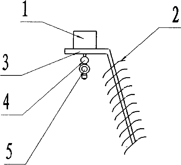
[0014] The present invention is matched with boom sprayer and used, as figure 1 As shown, it includes: truss 1, grid 2, frame 3, spray bar 4, spray head body 5 and other components.

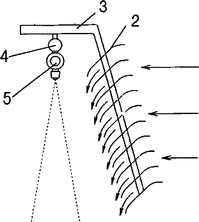
[0015] The main anti-drifting part of the grid cover is composed of a group of grids 2, and a group of diversion channels are formed between the grids, which can change the direction of movement of the horizontal airflow acting on the spray fan, so that the movement direction of the airflow is consistent with the mist flow during spraying. movement in the same direction, thus forming a wind curtain, such as figure 2 As shown, it can not only prevent the front horizontal airflow from acting on the mist flow, and blow the fine mist droplets away from the spray fan to cause drifting, but also can force the mist droplets to enter the canopy, increasing the penetrati...


PUM


Abstract

The invention discloses a spraying device of grid-typed anti-drift cover cap, which belongs to the field of spraying systems. The spraying device comprises parts such as a truss, grids, a frame, a spray rod, a nozzle body, etc. The grids serve as anti-drift components; and a group of grids form the grid-typed cover cap, the grid-typed anti-drift cover cap is obliquely fixed with the oblique part of the frame in an intersected way so as to form a group of diversion channels between the grids so that the movement direction of the horizontal air flow acting on a spraying sector can be changed, the air flow moves in the same direction as that in which the fog does so as to form an air curtain for stopping fine fog drops from being drifted. Furthermore, the air curtain can force the fog drops to enter a canopy layer, thereby improving the penetrability of fine fog drops in the canopy layer and improving the effect of depositing liquid medicine in the canopy layer. As the fine fog drops can be effectively utilized and a small-amount spraying can be realized, the usage amount of the pesticides is reduced and the safety of foods, human bodies and environment are improved.

Description

technical field [0001] The invention belongs to the field of spraying systems, and particularly relates to a spraying device for a grid-type anti-drift cover. Specifically, a set of grids is used to form a series of diversion channels to change the direction of movement of the horizontal airflow acting on the spray fan surface, so that The movement direction of the airflow is the same as that of the mist flow during spraying, so as to prevent the loss of fine mist droplets. Background technique [0002] my country's pesticide application equipment is guided by high-capacity pesticide application technology. The amount of spray liquid per unit area is large, and the sprayed droplets are thick, which is difficult to adapt to the biological characteristics of the surface of the control object. Rolling down, the droplet adhesion effect is poor, resulting in the loss of a large amount of liquid medicine. Therefore, in order to fundamentally solve the problem of low effective utili...

Claims


Application Information

Patent Timeline
Patent Type & Authority Applications(China)
IPC IPC(8): B05B9/00B05B15/04
Inventor 宋坚利何雄奎
Owner CHINA AGRI UNIV
Why Eureka
Try Eureka