Simple ultra-stable stage with built-in fiduciary markers for fluorescence nanoscopy

a fluorescence nanoscopy, ultra-stable technology, applied in the direction of microscopes, ceramic shaping apparatuses, instruments, etc., can solve the problems of difficult effective use, high cost, and complex equipment, and achieve the effect of simple provision, convenient detection, and efficient us

Active Publication Date: 2014-05-06
THE BOARD OF TRUSTEES OF THE UNIV OF ILLINOIS
View PDF8 Cites 28 Cited by
  • Summary
  • Abstract
  • Description
  • Claims
  • Application Information

AI Technical Summary

Benefits of technology

[0008]The invention provides a microscope stage mount with built-in fiduciary markers for fluorescence microscopy, methods of making and using the mount. A major advantage of our invention is the efficient, cost-effective and simple provision of fiduciary markers that are stably fixed to the plate (e.g. coverslip) and easily detectable. Our system works well both in vitro and on living cells, in 1 and 2-photon excitation schemes, and in physiological tissues.
[0011]The precise pillar size can vary, but the pillars of a given mount should be defined (nonrandom and predetermined in size and shape) and are preferably relatively uniform in size and shape and evenly-spaced apart to facilitate calibration. Exemplified below are pillars nominally about 1 μm across and about 1 μm high (measured by us to be less than 1 μm, about 0.885 μm); however, pillars of nominal dimensions of about 0.5, 1.5, 2, 2.5, 3, 3.5 and 4 μm (x, y and z dimensions) work well, and the height (z-dimension) need not be the same as the side dimensions.
[0017]In the simplest scheme the system “passively” measures the microscope stage, which is then divided or subtracted out from the visible fluorescence of interest. This mode does not require any fancy stages—in fact, one can get nanometer accuracy with the usual commercially-available stages—converting a “microscope” into a “nanoscope”. In another embodiment it is used to “actively” feedback a signal to microscope stages to minimize stage drift. Hence, in particular embodiments, the subtracting step occurs in real time, providing a continuous feedback signal to a drift corrector which in turn reduces drift of the microscope stage.

Problems solved by technology

However, these methods are expensive, require sophisticated equipment and / or are difficult to use effectively.
Simpler gold particles or beads can be used, as seen with both PALM and STORM for example, but these have their own limitations: it is awkward to place the correct amount of beads, to get them to stick so they don't move with respect to the slide, to interrogate them at a wavelength that does not interfere with the sample, and to make them biologically and chemically inert with respect to the sample.

Method used


Image

  • Simple ultra-stable stage with built-in fiduciary markers for fluorescence nanoscopy
  • Simple ultra-stable stage with built-in fiduciary markers for fluorescence nanoscopy
  • Simple ultra-stable stage with built-in fiduciary markers for fluorescence nanoscopy

Examples


Embodiment Construction

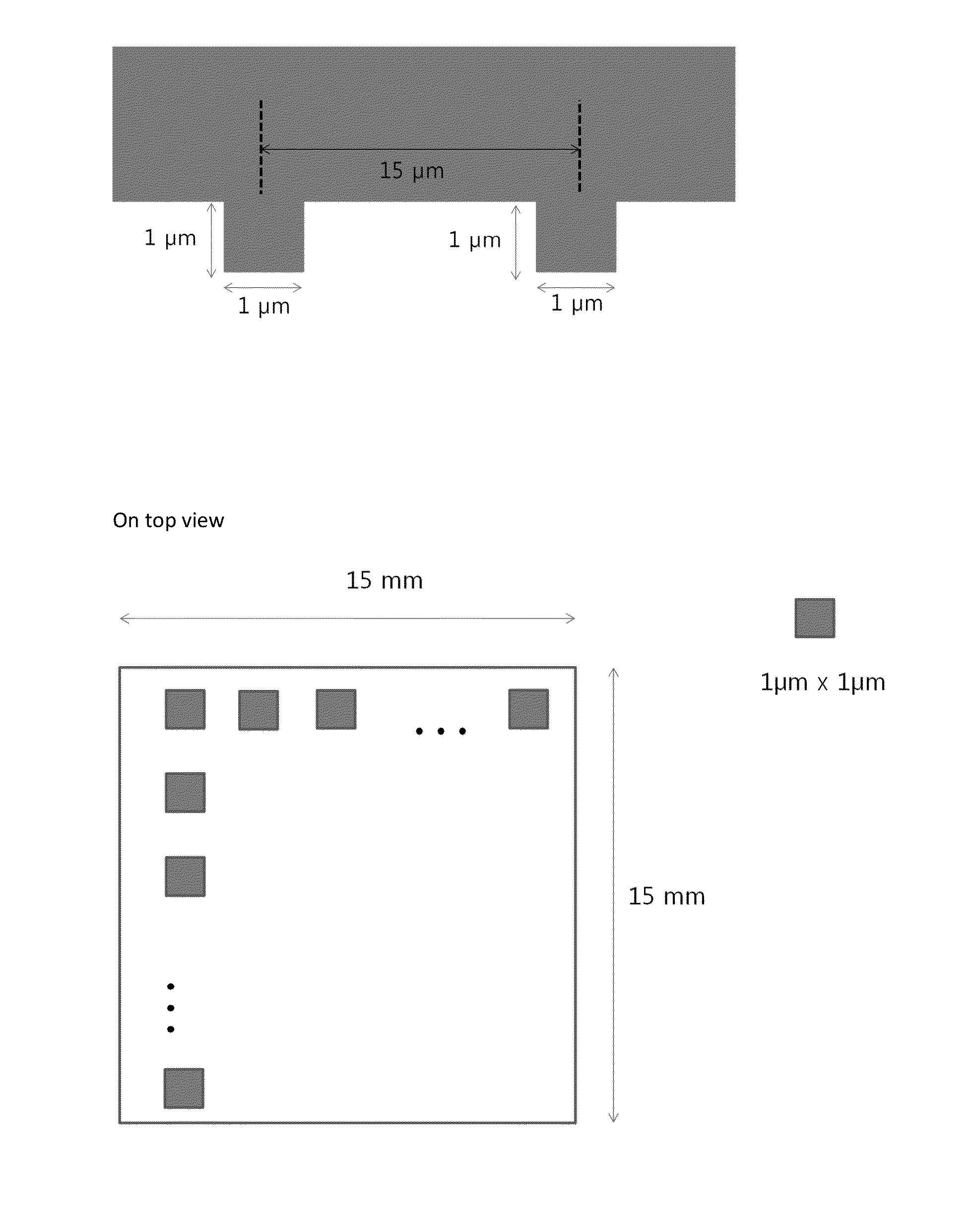
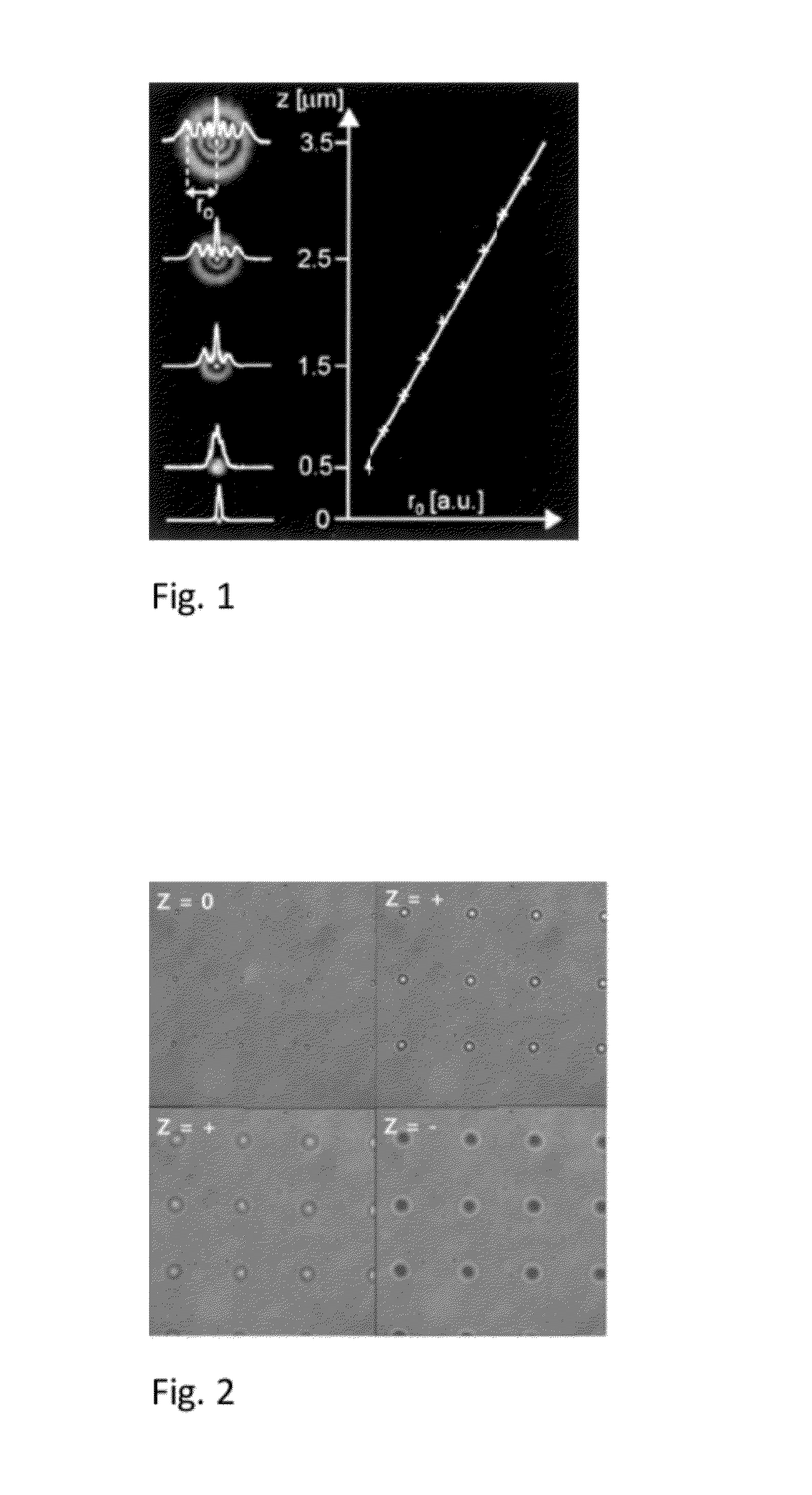
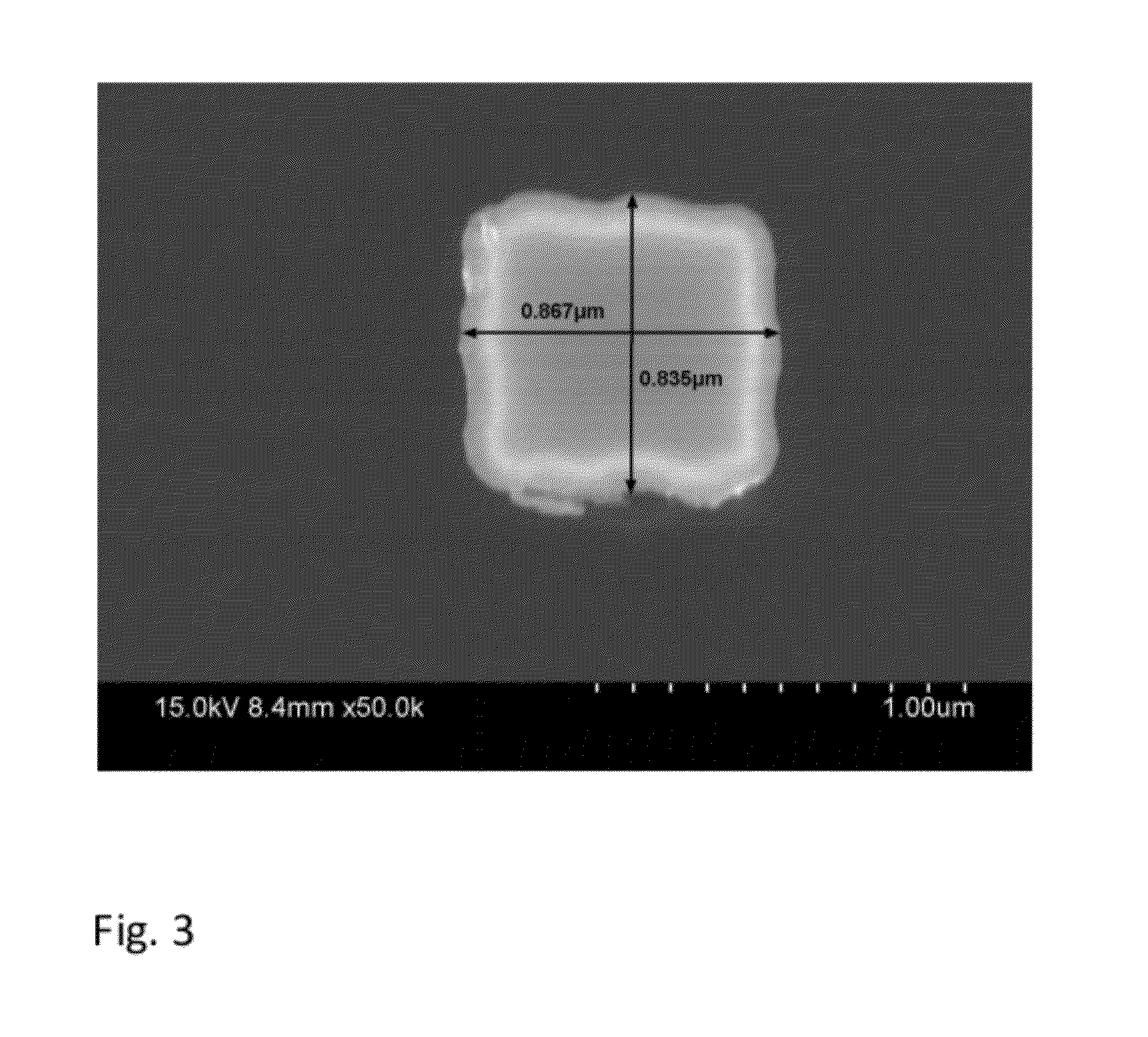
[0023]We placed PMMA pillars, approximately 1 μm in diameter, and 1 μm in tall, every 15 μm—these numbers are adjustable. These pillars are fiduciary markers that do not move with respect to the coverslip and are immune to relevant biological and chemical processes. By exciting these with (near) intra-red (IR) light, they undergo significant diffraction, which we used to track the fiduciary markers. Furthermore, by shining IR light in a way which is defocused at the plane of the fiduciary markers, we can easily get the 3-dimensional (x, y, z) position of these pillars. Finally, because the (biological) signal of interest is visible fluorescence, the biological signal can be easily separated out from the IR signal coming from the fiduciary markers; hence they both can be read out and do not interfere with each other. The IR signal is read out by a simple, inexpensive CCD detector, and either used in a passive or active mode.

[0024]The wavelength of the IR light depends on the visible ...


PUM

PropertyMeasurementUnit
wavelengthaaaaaaaaaa
diameteraaaaaaaaaa
wavelengthaaaaaaaaaa

Abstract

An improved microscope stage mount with built-in fiduciary markers is used for fluorescence microscopy, and comprises: (a) an optically-transparent glass plate adapted for specimen mounting and microscope viewing and comprising a specimen mounting area; and (b) a defined and ordered, two-dimensional microscopic array of fiduciary markers, wherein the markers are polymeric pillars affixed to the plate about the specimen mounting area, wherein the markers provide a three-dimensional spatial reference for the specimen.

Description

[0001]This invention was made with government support under grant / contract number GM068625 awarded by the National Institutes of Health and grant / contract number DBI0649779 awarded by the National Science Foundation. The government has certain rights in the invention.FIELD OF THE INVENTION[0002]The field of the invention is calibration tools for high-resolution fluorescence microscopy.BACKGROUND OF THE INVENTION[0003]A general goal in optical fluorescence microscopy is to improve the resolution much below the optical limit, which is about 250 nm Recent techniques, such as STORM (Bates, et al., Science, 317, p. 1749-53, 2007) and PALM (Betzig et al., Science, 313, p. 1642-5, 2006) have achieved ˜20 nm. In general, visible fluorescence is used to track the motion or position of a biological marker of interest. But in order to get such fine resolution (˜20 nm), one must be sure that either that the stage does not undergo motion greater than this amount, or to account for this motion an...

Claims


Application Information

Patent Timeline
Patent Type & Authority Patents(United States)
IPC IPC(8): G02B21/34G02B21/00G02B27/32
CPCG02B27/32G02B21/26G02B21/16G02B21/00G02B21/34
Inventor SELVIN, PAUL R.LEE, SANG HAK
Owner THE BOARD OF TRUSTEES OF THE UNIV OF ILLINOIS
Why Eureka
Try Eureka