Power distribution network electromagnetic optimization dynamic loss reduction method, system and synthetic loss reduction system
A distribution network and loss reduction technology, applied in the direction of system integration technology, information technology support system, multi-phase network asymmetry reduction, etc., can solve the problems of increasing loss, burning, zero-crossing noise, etc.
- Summary
- Abstract
- Description
- Claims
- Application Information
AI Technical Summary
Problems solved by technology
Method used
Image
Examples
Embodiment 1
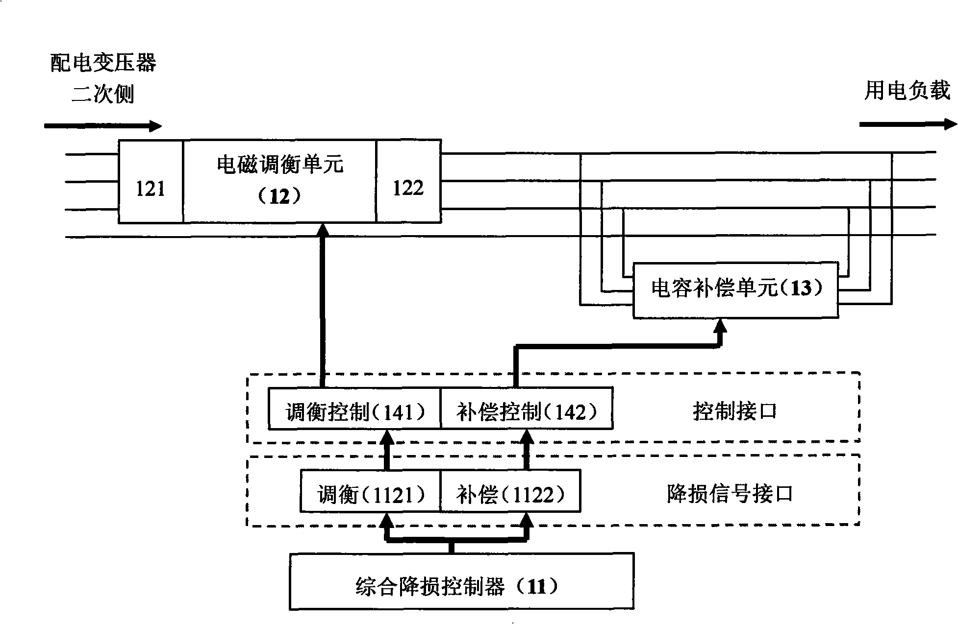
[0069] Embodiment 1: This embodiment is an implementation of the method for dynamic loss reduction of electromagnetic balancing in the distribution network. The electromagnetic balancing unit is connected in series at the output end of the secondary side of the distribution transformer. The electromagnetic balancing unit here includes a jumper , A three-phase winding unit mixed and wound on three sets of magnetic columns made of silicon steel or silicon steel sheets laminated. Each phase of the three-phase winding unit contains a certain number of coils wound in series on two adjacent magnetic columns The coil on the two adjacent magnetic columns, one is the main body magnetic column, and the other is the jumper magnetic column. The coil on the main body magnetic column is wound in a clockwise direction, and the coil on the bridged magnetic column is wound in a counterclockwise direction. , the number of coil turns is calculated according to the requirements of the loss reducti...
Embodiment 2
[0072] Embodiment 2: The method for dynamic loss reduction of distribution network electromagnetic balancing in this embodiment adds a capacitor compensation unit on the basis of Embodiment 1. By connecting the capacitor compensation unit in parallel in the three-phase circuit at the output end of the secondary side of the distribution transformer, according to the detected power factor, reactive power, voltage, and capacitance value parameters, when the power factor is not in the range of 0.85 to 0.95, When the voltage does not exceed the preset value (can be set to +7% or -10% of the rated voltage of the transformer), and the required reactive power is greater than the capacitance of the proposed capacitor, the corresponding capacitor is input through the compensation control switch To the power grid to compensate for the lack of reactive power and improve the power factor; when the voltage exceeds the preset value or the power factor is greater than the upper limit of 0.95, ...
Embodiment 3
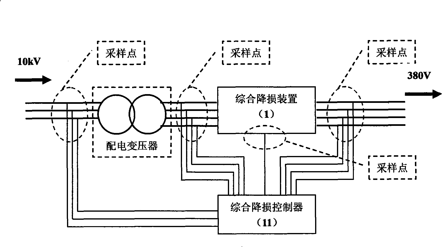
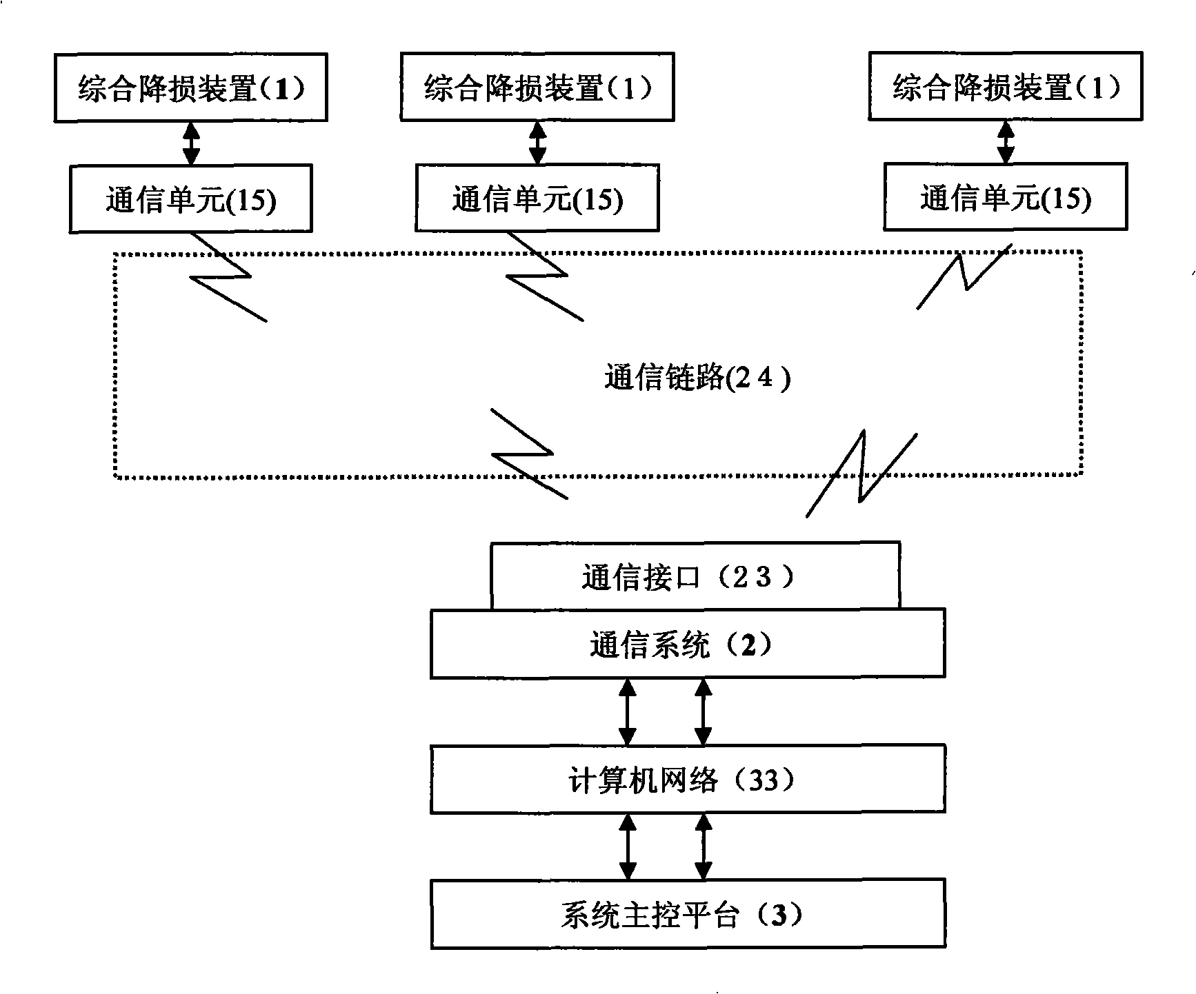
[0073] Embodiment three: see figure 1 , figure 2. In this embodiment, the dynamic loss reduction system for distribution network electromagnetic regulation and balancing includes a comprehensive loss reduction device 1 connected in series in the output circuit on the secondary side of the distribution transformer. The comprehensive loss reduction device 1 includes a comprehensive loss reduction controller 11, an electromagnetic balancer Unit 12, wherein the electromagnetic balancing control output interface 1121 of the comprehensive loss reduction controller 11 is connected to the electromagnetic balancing unit 12 through the balancing control interface 141, and the input terminal 121 of the electromagnetic balancing unit 12 is connected to the three terminals on the secondary side of the distribution transformer. The phase output terminal, the output terminal 122 of the electromagnetic balancing unit 12 is connected with the electric load; the comprehensive loss reduction ...
PUM
 Abstract
Description
Claims
Application Information
 - R&D
- Intellectual Property
- Life Sciences
- Materials
- Tech Scout
- Unparalleled Data Quality
- Higher Quality Content
- 60% Fewer Hallucinations
Browse by: Latest US Patents, China's latest patents, Technical Efficacy Thesaurus, Application Domain, Technology Topic, Popular Technical Reports.
© 2025 PatSnap. All rights reserved.Legal|Privacy policy|Modern Slavery Act Transparency Statement|Sitemap|About US| Contact US: help@patsnap.com


