Adjustable reactor type voltage regulating and stabilizing device

A technology of voltage stabilizing device and reactance adjustment, which is applied in the field of voltage stabilizing device and adjustable reactor type voltage regulation

Inactive Publication Date: 2014-03-26
HARBIN PATEERN SCI & TECH
View PDF5 Cites 1 Cited by
  • Summary
  • Abstract
  • Description
  • Claims
  • Application Information

AI Technical Summary

Problems solved by technology

[0003] The present invention overcomes the deficiency of the existing saturable reactor type voltage regulating and stabilizing device, and provides an adjustable reactor type voltage regulating and

Method used


Image

  • Adjustable reactor type voltage regulating and stabilizing device
  • Adjustable reactor type voltage regulating and stabilizing device

Examples


Embodiment Construction

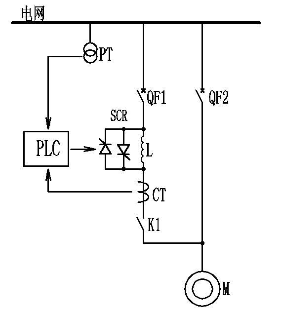
[0011] exist figure 1 Among them, L is a reactor, SCR is a thyristor, QF1 is a running switch, QF2 is a backup switch, K1 is an isolation switch, PT is a voltage transformer, CT is a current transformer, PLC is a programmable controller; one end of the backup switch QF2 Connected to the power grid, one end is connected to the power load M; the upper end of the reactor L is connected to the power grid through the running switch QF1, and the lower end of the reactor L is connected to the power load M through the isolation switch K1; the positive and negative parallel thyristor SCR and the reactor L forms a closed loop.

[0012] Before putting into operation, the standby switch QF2 is disconnected, the isolating switch K1 is closed, and the running switch QF1 is closed during operation. The reactor L is put into operation, and the thyristor SCR is in the cut-off state due to no trigger signal. Because the impedance of the reactor L is large, the power load The terminal voltage o...


PUM


Abstract

The invention provides an adjustable reactor type voltage regulating and stabilizing device, and belongs to the technical field of power electronics. Compared with a saturation reactor type voltage regulating and stabilizing device, the adjustable reactor type voltage regulating and stabilizing device has the characteristics of precise control, large adjustment range, high repeatability precision and low loss.

Description

technical field [0001] The invention belongs to the technical field of power electronics, and in particular relates to an adjustable reactor type voltage regulating and stabilizing device. technical background [0002] High-power electrical occasions such as heating furnaces, heat treatment furnaces, and high-power rectifier power supplies often require high-power controls such as voltage regulation and voltage stabilization to improve product quality and reduce losses. At present, there is a saturable reactor-type voltage regulation and voltage stabilization device that is widely used, but there are problems such as inaccurate control, small adjustment range, poor repeatability, and large self-loss. Contents of the invention [0003] The present invention overcomes the deficiency of the existing saturable reactor type voltage regulating and stabilizing device, and provides an adjustable reactor type voltage regulating and stabilizing device which can smoothly and stepless...

Claims


Application Information

Patent Timeline
IPC IPC(8): H02J3/12
Inventor 潘家忠王宇李天昊
Owner HARBIN PATEERN SCI & TECH
Why Eureka
Try Eureka