
Vertical roller mill with side shifting roll-changer

A vertical roll mill and replacement technology, which is applied in the direction of metal rolling stand, metal rolling mill stand, metal rolling, etc., can solve the problem of increasing the amount of maintenance spare parts, the consumption of spare parts, the cumbersome operation of changing rolls in the rolling mill, and the easy damage of the connecting device and other problems, to achieve the effect of light weight, convenient maintenance and repair, and low labor intensity

Inactive Publication Date: 2008-12-17
TIANJIN TIANZHONG ZHONGZHI TECH ENG CO LTD
View PDF0 Cites 11 Cited by
  • Summary
  • Abstract
  • Description
  • Claims
  • Application Information

AI Technical Summary

Problems solved by technology

[0004] Rolls are prone to wear during production and must be replaced
The existing technology has the following defects in the replacement of rolls: when replacing the rolls, first loosen the anchor bolts and couplings of the transmission distribution box, separate the distribution box to both sides, and let the space for lifting the roll system from above, Then lift out the whole roll system from above to replace the rolls
This type of structure of the vertical roll mill has resulted in cumbersome roll changing operations and long roll changing time; the spline connection parts need to be disassembled and assembled frequently, and the connecting device is easily damaged, which increases the maintenance amount and the consumption of spare parts and spare parts

Method used


Image

  • Vertical roller mill with side shifting roll-changer
  • Vertical roller mill with side shifting roll-changer
  • Vertical roller mill with side shifting roll-changer

Examples


Embodiment Construction

[0030] Embodiments of the present invention will be further described below in conjunction with the accompanying drawings.

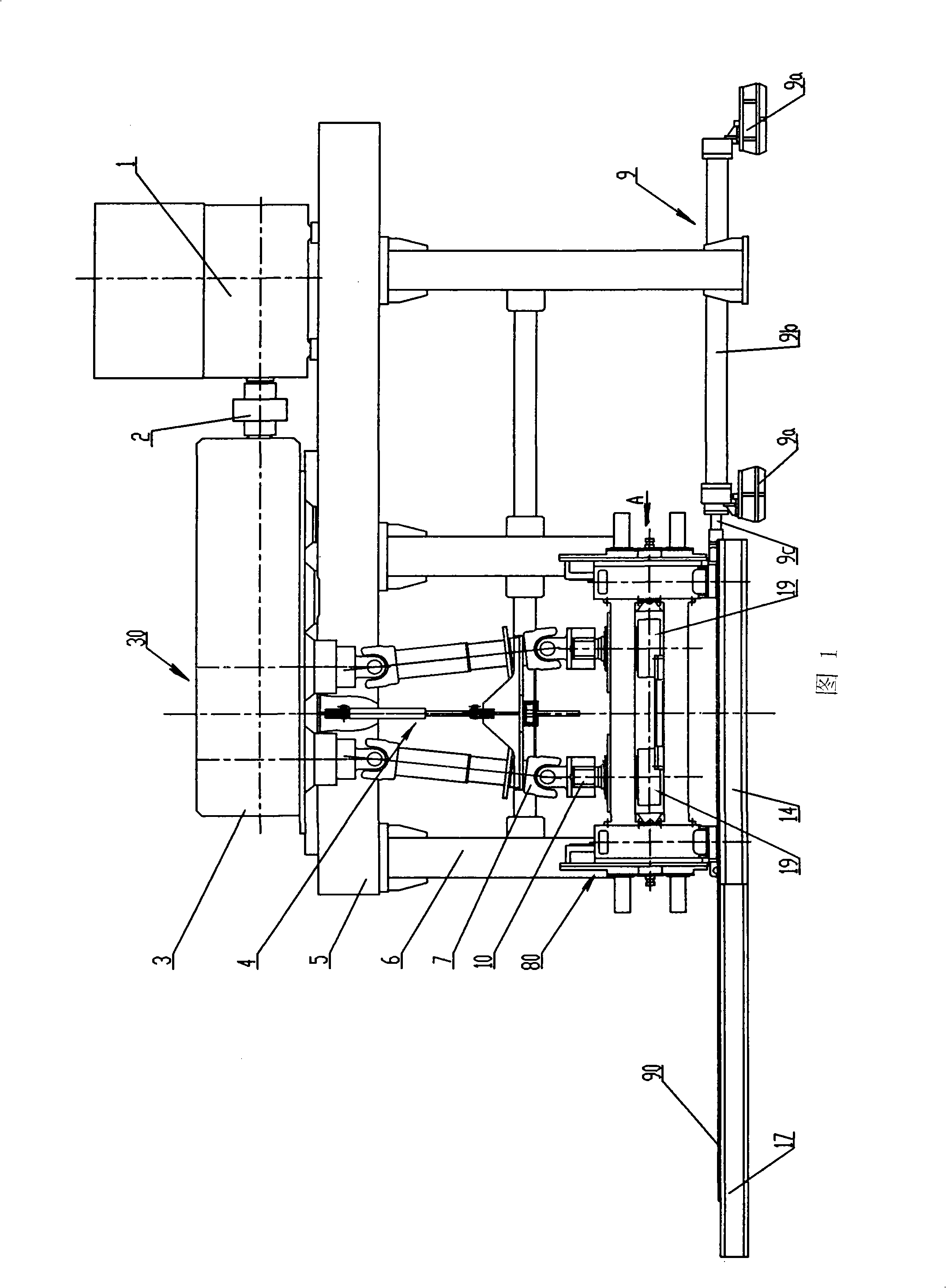
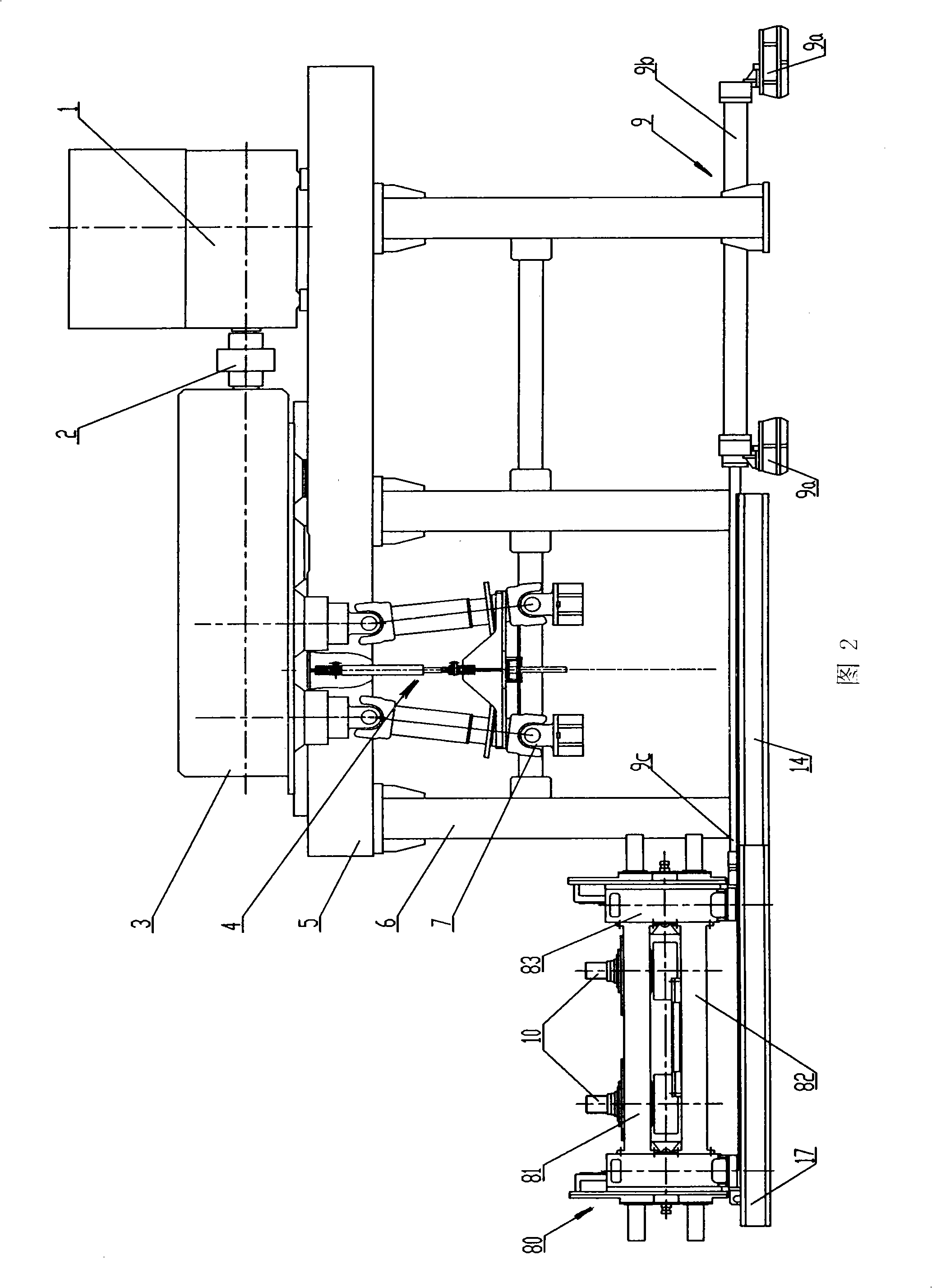
[0031] As shown in Fig. 1 and Fig. 2, the present invention provides a vertical rolling mill with a side shifting roll changing device. The vertical rolling mill includes: a transmission platform 5 supported by a column 6, a power output part 30, a The rolling mill body 80 of the series 10.

[0032] The vertical rolling mill also includes a push roll part 9 and a cardan shaft lifting part 4 that push the rolling mill body 80 to move horizontally.

[0033] The roll pushing part 9 is arranged on one side of the rolling mill body 80 , and a roll changing platform 17 is arranged on the other side of the rolling mill body 80 . A lining plate 90 is installed on the roll changing platform 17 , and the lining plate 90 is convenient for the roll pushing part 9 to smoothly push the rolling mill body 80 on the roll changing platform 17 .

[0034] The cardan shaft...


PUM


Abstract

The invention discloses a vertical mill provided with a sideway roll changing rig. The vertical mill comprises a transmission platform, a power output part and a mill body and also comprises a push roller part for pushing the mill body to move horizontally and a lifting part of universal shaft. The push roller part is arranged at one side of the mill body and a roll changing platform is arranged at the other side of the mill body; the lifting part of the universal shaft is arranged at the upper part of the mill body and is connected with two universal shafts and the upper end of the lifting part of the universal shaft is arranged on the transmission platform; one end of each of two universal shafts is respectively connected with the end parts of a couple of roll systems and the other end of each of two universal shafts is respectively connected with the power output part which is arranged on the transmission platform. The vertical mill has the advantages that replacing the roll refers to moving the mill body provided with roll systems as a whole to the outside of the vertical mill for replacement, no obstacle is attached to the operation space for roll replacement, auxiliary equipment is not required, with convenience and rapidness ensured. The vertical mill has the advantages of simple structure, convenient maintenance and overhaul, low labor intensity, etc.

Description

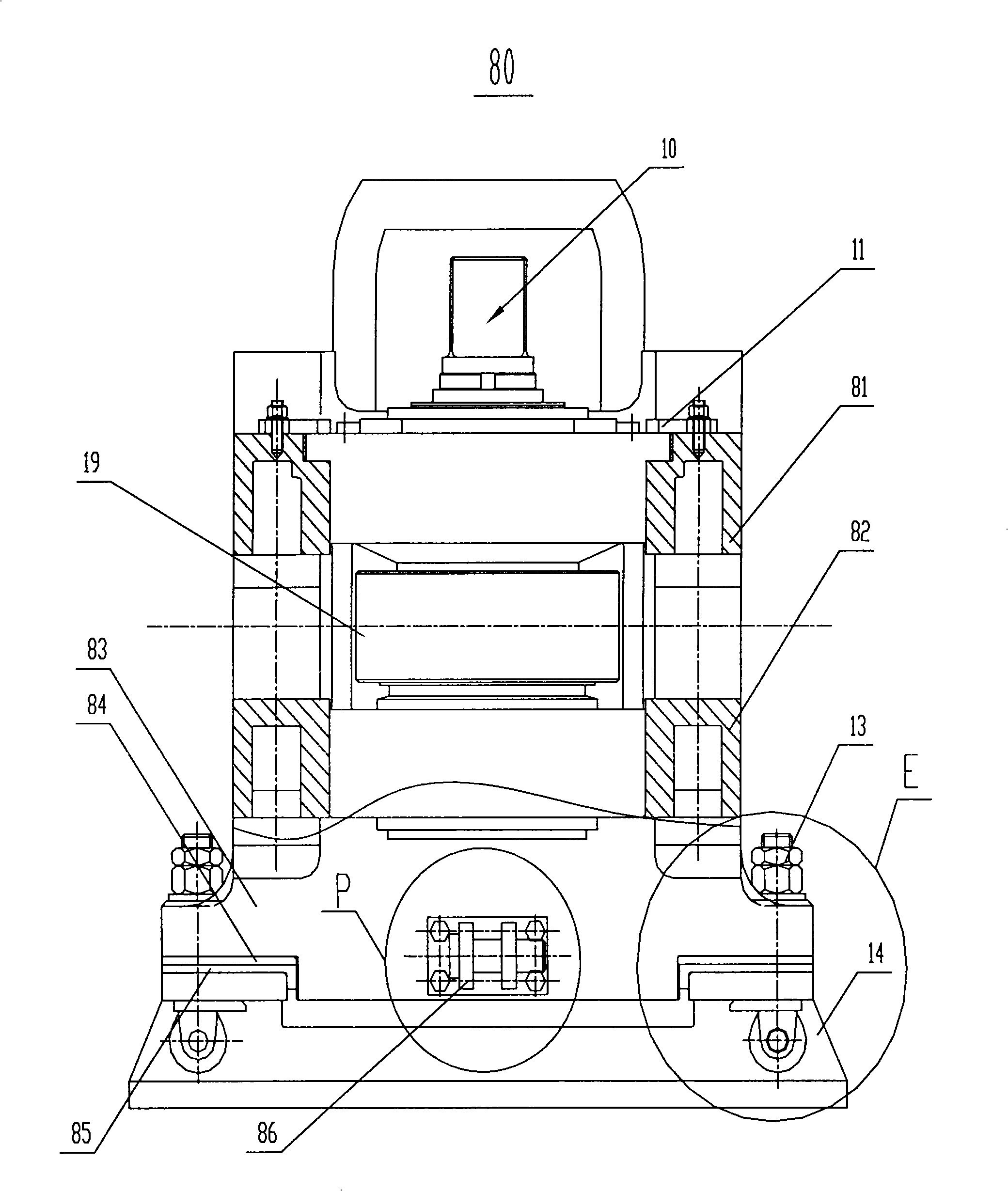
technical field [0001] What the present invention relates to is vertical rolling mill, what particularly relate to is the vertical rolling mill with side shifting roll changing device. Background technique [0002] The mill body of the vertical roller mill in the prior art is fixed on the foundation plate and cannot be moved, and a roll train including a pair of rolls is arranged in the mill body; the transmission distribution box including the cardan shaft is located above the mill body, including the transmission of the motor. The mechanism is located on the side of the mill body. When replacing the rolls, the rolls can only be pulled out from above the roll train. [0003] The structure of the rolling mill body of the prior art is the same as the rolling mill body structure of the present invention, as image 3 As shown, its structure includes: there are two frame main bodies 83 with a set distance therebetween; on both sides of the two frames 83, press plates 11 are res...

Claims


Application Information

Patent Timeline
IPC IPC(8): B21B31/10
Inventor 李萍
Owner TIANJIN TIANZHONG ZHONGZHI TECH ENG CO LTD
Learn More