Pneumatic tire
A technology of pneumatic tires and tires, which is applied to tire parts, rolling resistance optimization, road transportation emission reduction, etc., can solve the problems of low rolling resistance and safety, and achieve the effects of reducing rolling resistance, improving safety, and preventing static electricity accumulation
- Summary
- Abstract
- Description
- Claims
- Application Information
AI Technical Summary
Problems solved by technology
Method used
Image

Examples
Embodiment approach 1
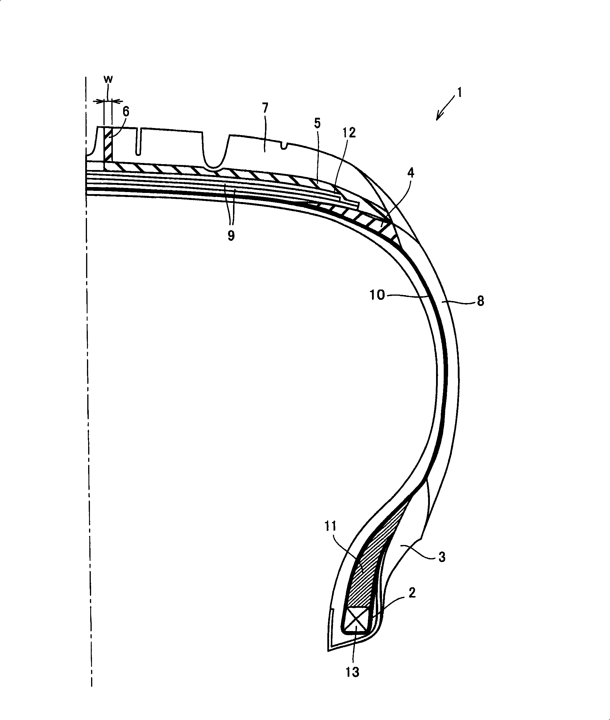
[0044] The structure of the pneumatic tire of the present invention is, for example, figure 1 The upper right half of the tire section is illustrated. The tire 1 has: a tread rubber 7 constituting a tread, a sidewall rubber 8 constituting a pair of sidewalls extending inwardly in the tire radial direction from both ends thereof, and a lap joint forming a lap joint portion located at the inner end of each sidewall. The part rubber 3, and the chafer rubber 2 that constitutes the chafer cloth located on the upper part of the rim. In addition, a carcass 10 is bridged between the clinch portion and the chafer, and at the same time, a buffer layer rubber 9 constituting a buffer layer is provided on the outer side of the carcass 10 in the tire radial direction. The carcass 10 is formed of one or more carcass plies on which a carcass cord is arranged, and the carcass plies pass from the tread through the sidewalls to the bead core 13 and from the upper end of the bead core 13 to the ...
Embodiment approach 2
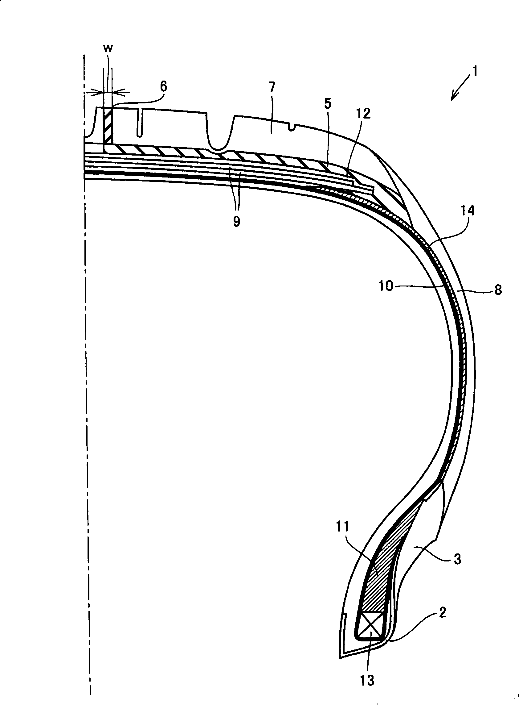
[0082] The structure of the pneumatic tire of the present invention is, for example, figure 2 The right half of the tire section is shown. The tire 1 has: a tread rubber 7 constituting a tread, a sidewall rubber 8 constituting a pair of sidewalls extending inwardly in the tire radial direction from both ends thereof, and a lap joint forming a lap joint portion located at the inner end of each sidewall. The part rubber 3, and the chafer rubber 2 that constitutes the chafer cloth located on the upper part of the rim. In addition, a carcass 10 is bridged between the beads on both sides, and at the same time, a buffer layer rubber 9 constituting a buffer layer is provided on the outer side of the carcass 10 in the tire radial direction.
[0083] The carcass 10 is formed of one or more carcass plies on which a carcass cord is arranged, and the carcass plies pass from the tread through the sidewalls to the bead core 13 and from the upper end of the bead core 13 to the tire. The p...
Embodiment approach 3
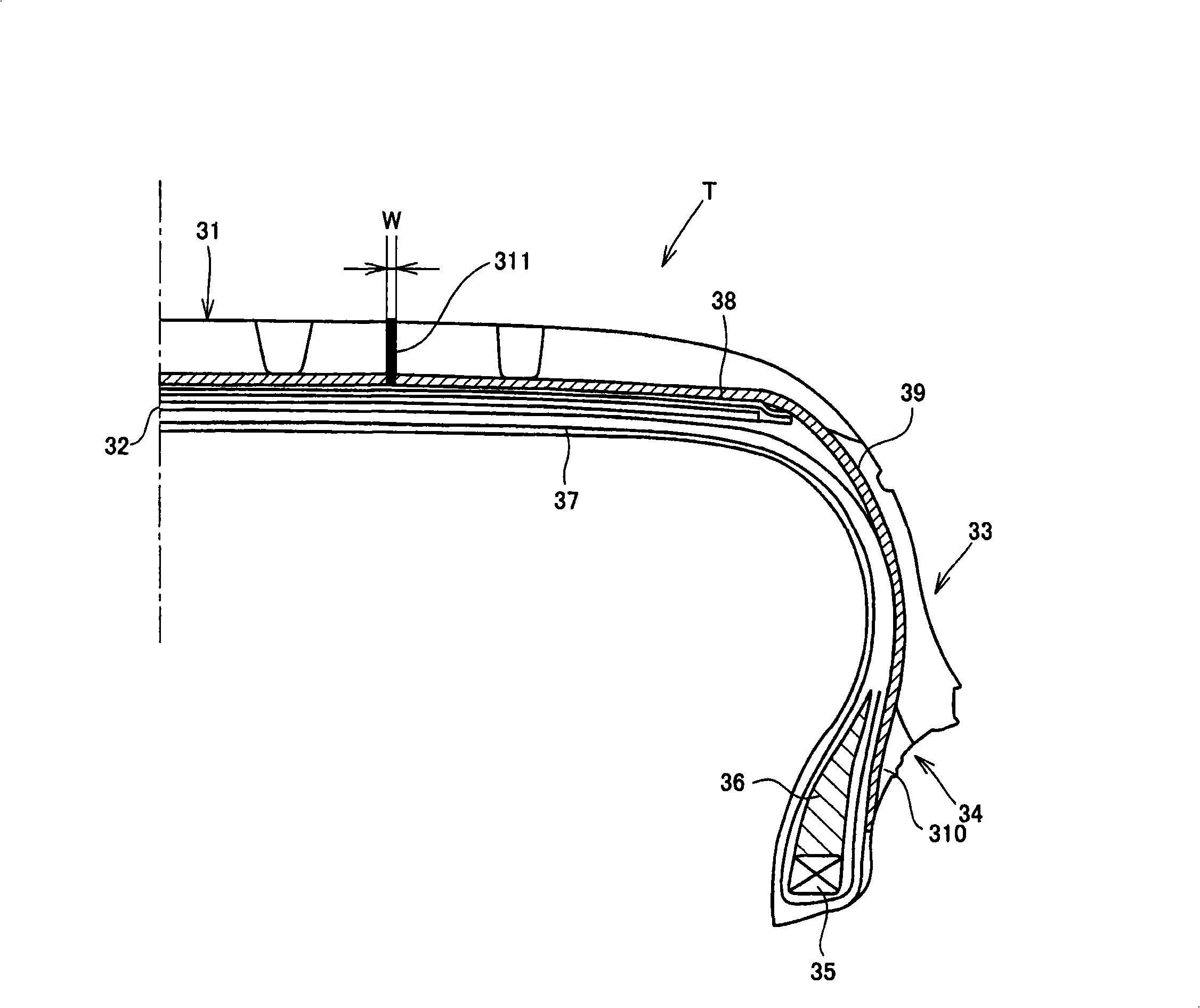
[0096] The structure of the pneumatic tire according to Embodiment 3 of the present invention is, for example, image 3 The right half of the tire section is illustrated. image 3 Among them, the pneumatic tire T has: a tread 31, a breaker layer 32, a sidewall 33, and a bead 34, and a non-connected tire belt 38 arranged outside the breaker layer, and a pair of bead cores 35 are folded and fixed at both ends. The carcass 37 and the triangular tape 36 extending from the upper side of the bead core 35 toward the sidewall 33. Especially in the present invention, the global conductive rubber 39 is provided between the carcass 37 and the side rubber, and between the breaker layer 32 and the tread 31 . Its upper end is connected to the conductive rubber 311 embedded in the tread 31 and exposed to the ground contact surface, and its lower end is connected to the clinch rubber 310 formed on the bead 34 .
[0097] By adopting the above structure, the static electricity generated by th...
PUM
| Property | Measurement | Unit |
|---|---|---|
| Volume intrinsic resistance | aaaaa | aaaaa |
| Volume intrinsic resistance | aaaaa | aaaaa |
| Thickness | aaaaa | aaaaa |
Abstract
Description
Claims
Application Information
 - Generate Ideas
- Intellectual Property
- Life Sciences
- Materials
- Tech Scout
- Unparalleled Data Quality
- Higher Quality Content
- 60% Fewer Hallucinations
Browse by: Latest US Patents, China's latest patents, Technical Efficacy Thesaurus, Application Domain, Technology Topic, Popular Technical Reports.
© 2025 PatSnap. All rights reserved.Legal|Privacy policy|Modern Slavery Act Transparency Statement|Sitemap|About US| Contact US: help@patsnap.com