
Controller for delaying accelerograph when stepping on by mistake

A time-delay controller and accelerator technology, which is applied in the layout of the power unit control mechanism, automatic starting device, transportation and packaging, etc., can solve the problems of not being able to brake in time, stepping on the accelerator by mistake, and injury, so as to avoid traffic accidents and increase The effect of safety and simple structure

Inactive Publication Date: 2011-09-07
李来友
View PDF0 Cites 0 Cited by
  • Summary
  • Abstract
  • Description
  • Claims
  • Application Information

AI Technical Summary

Problems solved by technology

[0002] In the prior art, through years of practice, the braking devices of motor vehicles have been basically perfected, and various types of braking devices have come out and been applied. still inevitable
[0003] As we all know, when driving a motor vehicle, you will often encounter various unexpected emergencies that require emergency braking, and drivers sometimes use the accelerator as a brake in an emergency and cause accidental depressing. Such accidents are not uncommon. The damage it causes is even greater than not being able to brake in time, especially when a novice is driving a motor vehicle on the road, it is often easier to step on the accelerator by mistake and cause an accident

Method used


Image

  • Controller for delaying accelerograph when stepping on by mistake
  • Controller for delaying accelerograph when stepping on by mistake

Examples


Embodiment 1

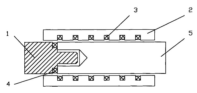
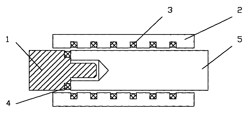
[0015] This embodiment provides a delay controller for misstepping the accelerator, and its structure schematic diagram is as follows figure 1 shown.

[0016] The device includes a sliding connecting rod 1, a positioning sleeve 2, a speed signal sensor, a hydraulic control connecting rod 5, and the speed signal sensor includes a speed signal generator 4 and a speed signal receiver 3; a sliding connecting rod 1, a positioning sleeve 2 and a hydraulic control connecting rod There is a sliding connection between the rods 5, and the speed signal generator 4 is arranged outside the end of the sliding connecting rod 1 close to the hydraulic control connecting rod 5; the inside of the positioning sleeve 2 is sequentially provided with at least two speed signal receivers starting from the end close to the sliding connecting rod 1. The device 3, the speed signal generator 4 and the speed signal receiver 3 move with the relative movement between the positioning sleeve 2 and the sliding ...

Embodiment 2

[0021] This embodiment provides another installation method of the speed signal generator 4 and the speed signal receiver 3: wherein, at least two speed signal receivers 3 are arranged on the sliding link 1, and the inside of the positioning sleeve 2 fixes the speed signal generator 4. In this way, when the relative motion speed between the speed signal generator 4 and the approaching speed signal receiver 3 is greater than or equal to the sensing speed set by the approaching speed signal receiver 3, the speed signal sensor controls the hydraulic control Rod 5 pushes back sliding connecting rod 1 and accelerator pedal is returned to original position. At the same time, the speed signal sensor controls the action of the braking system to stop the vehicle. On the contrary, the accelerator continues to increase. And so on, until the refueling action ends or emergency braking.

[0022] It should be noted that when the hydraulic control connecting rod 5 pushes back to the slidin...


PUM


Abstract

The invention relates to a vehicle safety operation device, which aims at providing a delay controller when a throttle is stepped on by mistake. The device comprises a sliding connection rod, a locating sleeve, a speed signal sensor and a hydraulic control connection rod; wherein, the speed signal sensor comprises a speed signal generator and a speed signal receiver; the sliding connection rod, the locating sleeve and the hydraulic control connection rod are connected with each other in a sliding way; the speed signal generator is fixedly arranged on the sliding connection rod; the speed signal receiver is fixedly arranged on the locating sleeve; or the speed signal receiver is fixedly arranged on the sliding connection rod and the speed signal generator is fixedly arranged on the locating sleeve; the speed signal generator and the speed signal receiver move together with the relative movement between the locating sleeve and the sliding connection rod; the external connection end of the sliding connection rod is fixedly connected with a throttle pedal. The device can effectively avoid severe traffic accidents caused by stepping on the throttle by mistake when various vehicles are in emergency.

Description

technical field [0001] The invention relates to a safety operation device for a motor vehicle, and more specifically, the invention relates to a delay controller for a wrongly stepped accelerator. Background technique [0002] In the prior art, through years of practice, the braking devices of motor vehicles have been basically perfected, and various types of braking devices have come out and been applied. Still inevitable. [0003] As we all know, when driving a motor vehicle, you will often encounter various unexpected emergencies that require emergency braking, and drivers sometimes use the accelerator as a brake in an emergency and cause accidental depressing. Such accidents are not uncommon. The damage it causes is even greater than not being able to brake in time, especially when a novice is driving a motor vehicle on the road, it is often easier to step on the accelerator by mistake and cause an accident. Thereby need a kind of braking device that accelerator pedal ...

Claims


Application Information

Patent Timeline
Patent Type & Authority Patents(China)
IPC IPC(8): B60K26/02B60T7/12B60W10/06B60W10/18B60W10/184
Inventor 李来友
Owner 李来友
Learn More