
Hinged joint positioning apparatus

A positioning device and hinged technology, which is applied in the direction of building structure support, building structure support, construction, etc., can solve the problems of inconvenient operation and the lack of automatic positioning function of the positioning device

Active Publication Date: 2008-12-17
SUZHOU PICA ALUMINUM IND
View PDF1 Cites 5 Cited by
  • Summary
  • Abstract
  • Description
  • Claims
  • Application Information

AI Technical Summary

Problems solved by technology

[0003] The invention provides an improved hinged positioning device, the purpose of which is to solve the problem of inconvenient operation due to the lack of automatic positioning function when the existing positioning device is unlocked

Method used


Image

  • Hinged joint positioning apparatus
  • Hinged joint positioning apparatus
  • Hinged joint positioning apparatus

Examples


Embodiment

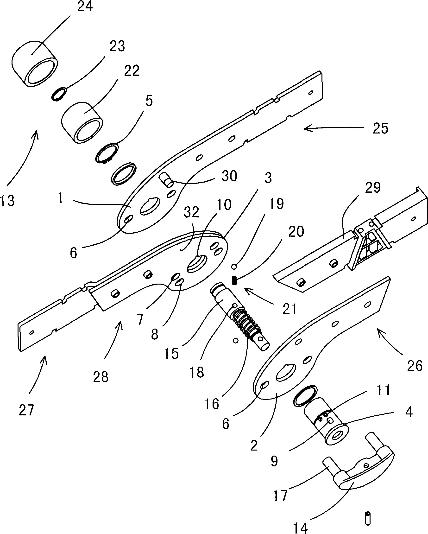
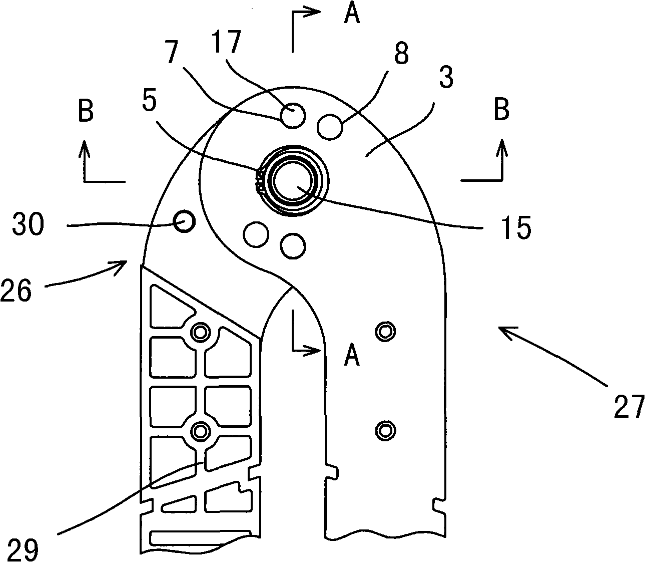
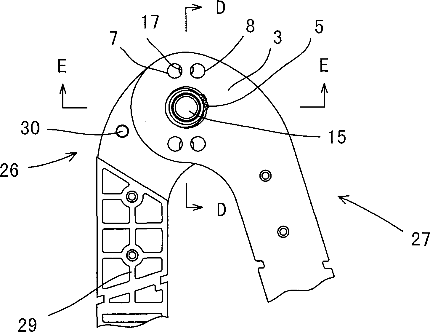
[0027] Example: as figure 1 , Figure 11 Shown is a kind of hinge positioning device 33 applied on the step ladder. The hinge positioning device 33 is composed of three parts: a hinge structure, a corner positioning structure and an unlocking positioning structure. The three parts are described below:

[0028] like figure 1 As shown, the hinged structure is composed of a first connecting body, a second connecting body and a central sleeve 4 . The first connecting body is composed of a left half piece 25 with an outer disk 1 on the head and a right half piece 26 with an outer disk 2 on the head. The outer disk 1 and the outer disk 2 are arranged parallel to each other and at intervals. A fixed connector 29 is disposed between the left half piece 25 of the first connecting body and the right half piece 26 of the first connecting body. The second connecting body is also composed of a left half piece 27 and a right half piece 28. Its head is provided with an inner disc 3, and...


PUM


Abstract

The invention relates to a hinging and positioning device which comprises a hinging structure. Between a first connector and a second connector, an outer disc and an inner disc pass through a central sleeve, thereby forming the hinging structure; a lock-pin linkage structure comprises a sliding shaft, a spring, a push handle, a pin boss and a pin body, and passes through the central sleeve; two first pinholes are arranged on the outer disc corresponding to the pin body; two second pinholes and two third pinholes are arranged on the inner disc; therefore, an angle positioning structure is formed and has one of three following operating conditions, that is, an included angle formed between the first connector and the second connector is 0 DEG, larger than 0 DEG and less than 180 DEG, or equal to 180 DEG. The device is characterized in that a spherical elastic locating piece arranged in the axial direction on the sliding shaft is utilized to be matched with a locating hole or a concave locating hole on the inner edge of the central sleeve to achieve axial positioning of the sliding shaft from the movement state to the unlock state. According to the technical proposal, an unlock positioning structure is added on the basis of the prior hinging structure and the angle positioning structure of the first connector and the second connector, thereby better solving the axial positioning problem of the sliding shaft relative to the central sleeve in the unlock state, and bring great convenience for use and operation.

Description

technical field [0001] The invention relates to a mechanical hinged positioning device, in particular to a hinged positioning device used in common tools such as ladders and scaffolding. Background technique [0002] A herringbone ladder is usually composed of a left half ladder and a right half ladder hinged at the top. In actual use, people often use the change of the opening angle of the ladder to adapt to different use states. In order to improve the safety of the stepladder when it is used in the open state, a hinge positioning device is usually designed at the hinge at the top of the stepladder. When the opening angle coincides with the positioning angle, it is fixed, so as to provide a reliable opening angle positioning. In the prior art, there are many kinds of hinged positioning devices used for ladders, one of which is called "multi-purpose ladder", the patent number is 03259706.1, and the Chinese utility model patent with the announcement number CN 2632283Y disc...

Claims


Application Information

Patent Timeline
Patent Type & Authority Applications(China)
IPC IPC(8): F16C11/00E06C1/02E04G1/02
Inventor 范刚
Owner SUZHOU PICA ALUMINUM IND
Learn More