TOFD ultrasonic non-destructive testing self-positioning fixture of welded rotor

A technology for welding rotors and non-destructive testing, which is used in the analysis of solids using sonic/ultrasonic/infrasonic waves, material analysis using sonic/ultrasonic/infrasonic waves, measuring devices, etc. Small space and other issues

Active Publication Date: 2015-05-06
东方电气集团科学技术研究院有限公司
View PDF10 Cites 4 Cited by
  • Summary
  • Abstract
  • Description
  • Claims
  • Application Information

AI Technical Summary

Problems solved by technology

[0003] In order to ensure the quality of the welded rotor, TOFD (Ultrasonic Time-of-Flight Diffraction) ultrasonic inspection of the weld is required during the manufacturing process, after the preparation is completed, and during service. TOFD ultrasonic inspection covers a large area and takes a long time for inspection.
Especially after the preparation is completed and in service, because the rotor is equipped with blades, the working space becomes extremely narrow
[0004] At present, there are already mature fixtures and testing systems for TOFD ultrasonic testing, but due to the special circumstances of the welding rotor application, none of the existing solutions can be used on the welding rotor
[0005] For example, the patent application number is 201010248503.2, the application date is August 14, 2010, and the invention patent named "Weld Ultrasonic Inspection and Scanning Device"; and the application number is 201310685223.1, the application date is December 13, 2013, named "Ultrasonic testing device for welded seam of thick-walled pipe". The scan data is unreliable and cannot be applied to welding rotors
[0006] Another example is that the patent application number is 201210192602.2, and the application date is June 12, 2012. It is an invention patent named "Intelligent Seam Tracking Ultrasonic Inspection Robot and Its Software Analysis System". Ultrasonic testing robots for positioning with ultrasonic probes cannot be identified by visual sensors after the welding seam of the welding rotor is processed, and the thickness of the welding rotor is fixed, so vision and thickness measurement methods cannot be used in the detection of welding rotors. Not suitable for use in welding rotor occasions

Method used


Image

  • TOFD ultrasonic non-destructive testing self-positioning fixture of welded rotor
  • TOFD ultrasonic non-destructive testing self-positioning fixture of welded rotor
  • TOFD ultrasonic non-destructive testing self-positioning fixture of welded rotor

Examples


Embodiment Construction

[0031] The present invention will be further described below in conjunction with the accompanying drawings.

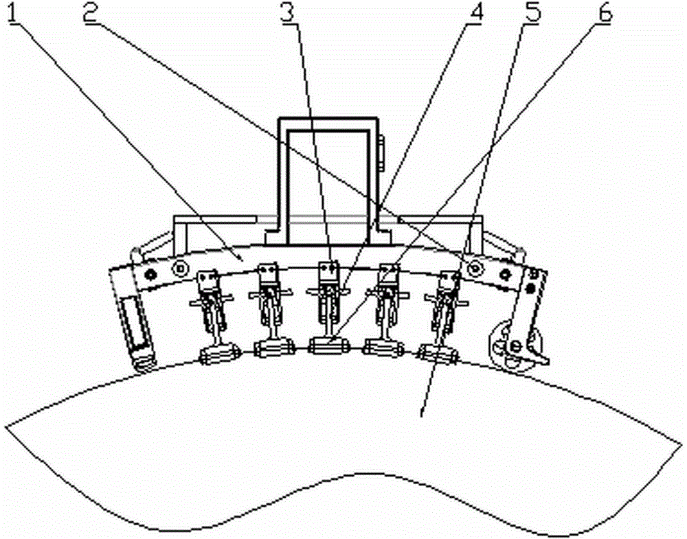
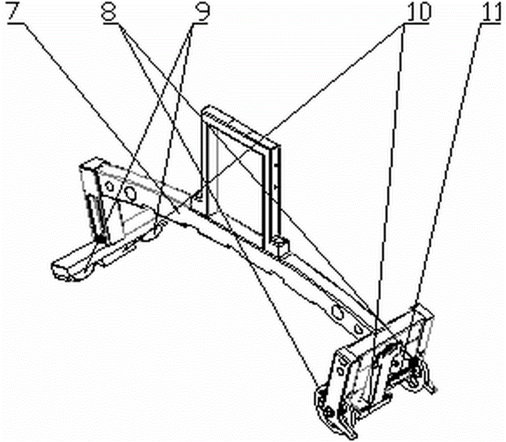
[0032] like figure 1 , figure 2 As shown, the welding rotor TOFD ultrasonic non-destructive testing self-positioning fixture is composed of an adsorption mobile platform 1, a positioning system 2, a fixture slide rail 3 and an adaptive fixture 4. The adsorption-type mobile platform 1 is adsorbed on the surface of the welding rotor 5, and can slide freely along the circumferential direction of the welding rotor 5; , to achieve axial positioning; the number of the fixture slide rails 3 is 5, which are respectively fixed on the adsorption mobile platform 1, and have a chute structure that can fix the self-adaptive fixture; the described self-adaptive fixture 4 has 10 , every two are symmetrically installed in the chute of a fixture slide rail, and clamp the TOFD detection wedge 6, making it contact with the surface of the welded rotor 5 for detection.

[0033] like ...


PUM


Abstract

The invention belongs to the field of testing robots and in particular relates to a TOFD ultrasonic non-destructive testing self-positioning fixture of a welded rotor. The fixture comprises an adsorption type mobile platform, a positioning system, a fixture slideway and a self-adaption fixture. The TOFD ultrasonic non-destructive testing self-positioning fixture of the welded rotor is used for clamping a TOFD ultrasonic non-destructive testing wedge block and a probe, the wedge block automatically adapts to surface angle of the welded rotor through two rotational degrees of freedom of the tail end of the fixture and spring force and is tightly pasted with the welded rotor, and axial positioning between the fixture and the welded rotor can be realized under action of the positioning system so that the welded block can accurately aim at a welded joint.

Description

technical field [0001] The invention belongs to the field of detection robots, in particular to a TOFD ultrasonic non-destructive detection self-positioning fixture for welding rotors. Background technique [0002] The rotor is the core component of the steam turbine, and it has many structural forms, such as integral forged rotors, sleeved rotors, welded rotors and combined rotors. Compared with the steam turbine rotors of conventional thermal power units, the steam turbine rotors of nuclear power plants are large in size and weight, and require high machining accuracy. Generally, welded rotors are used. [0003] In order to ensure the quality of the welded rotor, TOFD (time-of-flight diffraction) ultrasonic inspection of the weld is required during the manufacturing process, after the preparation is completed, and during the service process. The TOFD ultrasonic inspection covers a large area and requires a long time for inspection. Especially after the preparation is comp...

Claims


Application Information

Patent Timeline
Patent Type & Authority Applications(China)
IPC IPC(8): G01N29/265G01N29/07
Inventor 栗园园李永龙吴建东莫堃董娜肖唐杰张帆王重山王仕洋黄巍王佰昱
Owner 东方电气集团科学技术研究院有限公司
Why Eureka
Try Eureka