Bearing assembly

A technology for bearing devices and rolling bearings, applied to bearings, bearing elements, shafts and bearings, etc., can solve the problems of oil aging and service life impact, and achieve the effect of long service life

Active Publication Date: 2008-12-17
AB SKF
View PDF11 Cites 3 Cited by
  • Summary
  • Abstract
  • Description
  • Claims
  • Application Information

AI Technical Summary

Problems solved by technology

Depending on the stated parameters, a negative influence on the aging and service life of the oil of the bearing arrangement can sometimes also be achieved

Method used


Image

  • Bearing assembly
  • Bearing assembly
  • Bearing assembly

Examples


Embodiment Construction

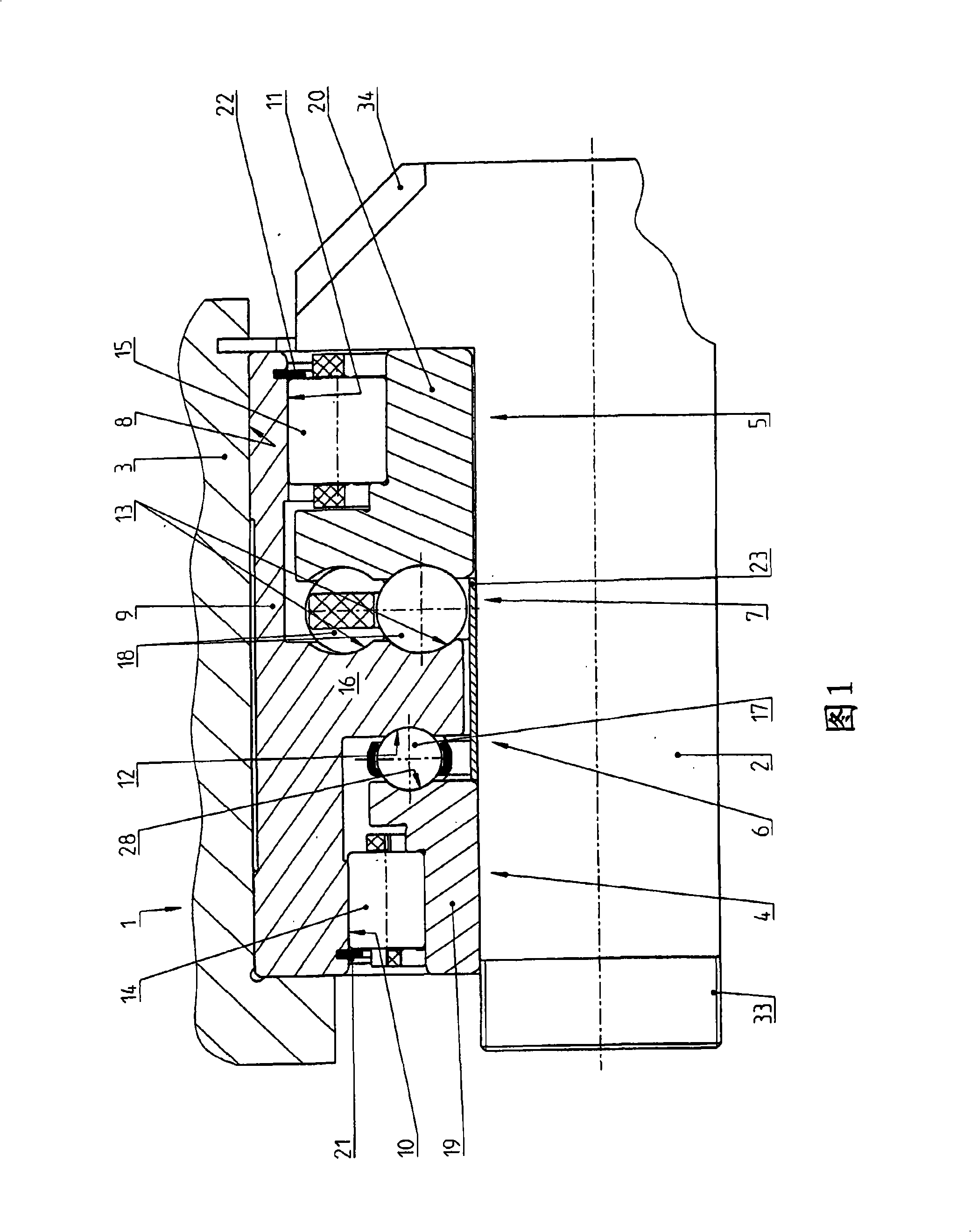
[0026] FIG. 1 shows a bearing arrangement 1 which radially and axially supports a shaft part 2 in the form of a bevel pinion shaft with a bevel pinion 34 relative to a housing 3 . The bearing arrangement 1 is located in a bore 8 in the housing 3 . The bearing arrangement 1 has two radial rolling bearings 4 and 5 designed as cylindrical roller bearings and two axial rolling bearings 6 and 7 designed as ball bearings. Both cylindrical roller bearings 4 , 5 and axial ball bearings 6 , 7 are each arranged at an axial distance from one another.

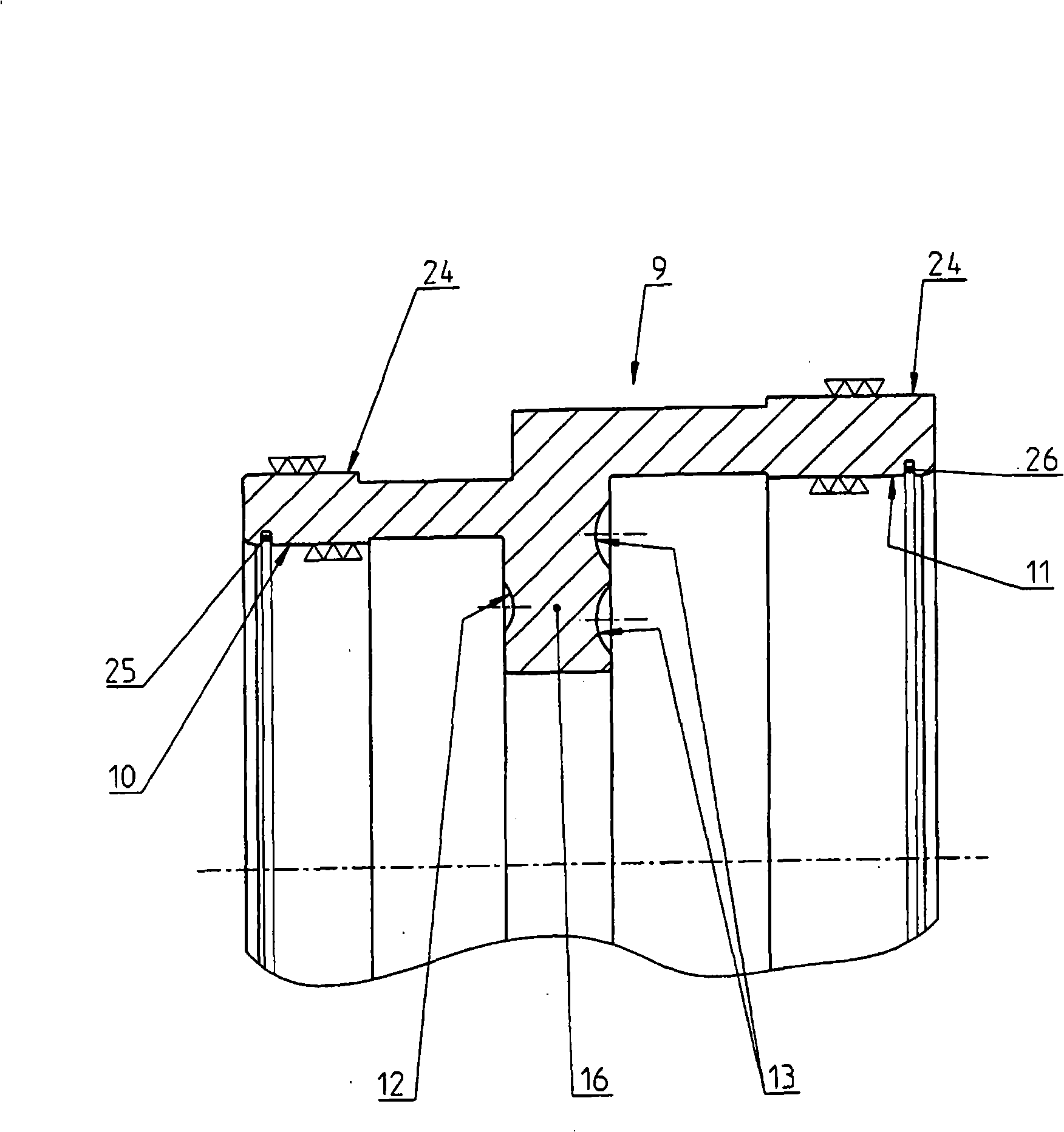
[0027] The bearing outer ring 9 is formed in one piece and has all the raceways 10 , 11 , 12 and 13 for the two cylindrical roller bearings and for the two axial ball bearings. The two cylindrical raceways 10 and 11 for the two cylindrical roller bearings are located in the region of the two axial ends of the bearing outer ring 9 . In the central region, the ring segment 16 extends radially inwards. Ball raceways 12 or 13 are formed on ...


PUM


Abstract

The invention relates to a bearing assembly (1) for radially and axially mounting a shaft part (2) relative to a housing (3). Said bearing assembly comprises two radial antifriction bearings (4, 5) which are disposed on the shaft part (2) at an axial distance from each other as well as two axial antifriction bearings (6, 7) that are arranged on the shaft part (2) at an axial distance from each other. In order improve mounting especially of a bevel pinion, the inventive bearing assembly further comprises an outer bearing ring (9) which is inserted into a housing (3) bore (8), is embodied as a monolithic component, and encompasses the tracks (10, 11, 12, 13) for the two radial antifriction bearings (4, 5) and the two axial antifriction bearings (6, 7).

Description

technical field [0001] The invention relates to a bearing arrangement for radially and axially supporting a bevel pinion of a vehicle main drive relative to a housing, wherein the bearing arrangement has two diameters arranged on the bevel pinion at an axial distance from each other. A rolling bearing and two axial rolling gears arranged on the bevel pinion with an axial distance from each other. Background technique [0002] To support the bevel pinion shaft in the vehicle main drive, in particular in the rear axle main drive, tapered roller bearings or angular contact ball bearings are usually used in O-shaped configuration. See JP06323329A for an example in this regard. Such a bearing arrangement is preloaded and provides an advantageous radial and axial fixation of the pinion shaft. [0003] Another support structure for a bevel pinion shaft is disclosed in JP2003-166627A. The shaft is supported here using two ball bearings and a cylindrical roller bearing. The beari...

Claims


Application Information

Patent Timeline
Patent Type & Authority Applications(China)
IPC IPC(8): F16C19/49F16C19/56F16H57/02F16H57/021
CPCF16C19/49F16C19/505F16H57/021F16C2361/61F16C33/585F16C33/60
Inventor T·沃尔夫
Owner AB SKF
Why Eureka
Try Eureka