

Improved hydraulic motor and assembly test method thereof
A hydraulic motor and improved technology, applied in the field of hydraulic system execution, can solve the problems of difficult adjustment of gaskets, prone to failure, and high labor intensity, and achieve the effects of reducing labor intensity, reducing excessive temperature, and facilitating heat dissipation.
- Summary
- Abstract
- Description
- Claims
- Application Information
AI Technical Summary
Problems solved by technology
Method used
Image

Examples
Embodiment Construction
[0037] In order to make the technical means, creative features, goals and effects achieved by the present invention easy to understand, the present invention will be further described below in conjunction with specific illustrations.
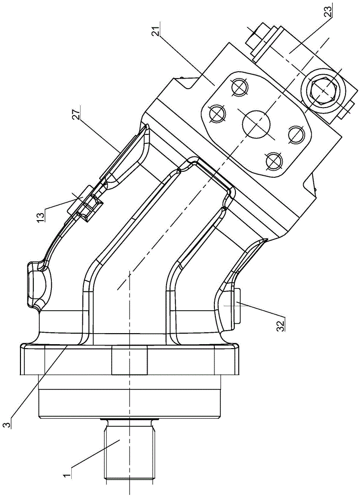
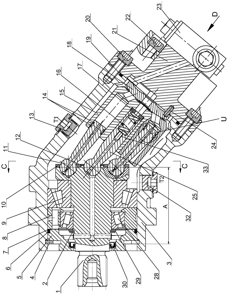
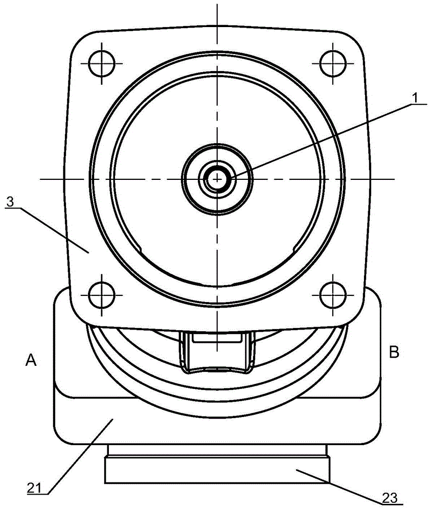
[0038] see Figure 1 to Figure 7 The improved hydraulic motor includes drive shaft 1, drive shaft retaining ring 2, motor housing 3, housing hole retaining ring 4, bearing gland 5, gland O-ring 6, axial clearance adjusting gasket 17. Intermediate pressure ring 8, rear tapered roller bearing 9, pressure plate 10, plunger 11, connecting rod ball head gap adjustment gasket 12, upper shell plug 13, plunger ring 14, cylinder body 15, Cylindrical spring 16, spring seat 17, oil distribution plate 18, housing seal O-ring 19, rear end cover screw 1 20, rear end cover 21, rear end cover screw 2 22, flushing valve 23, positioning pin 24, center connection Rod 25, flushing valve screw 26, label 27, front-end tapered roller bearing 28, axial clearance adjus...
PUM
 Abstract
Description
Claims
Application Information