Exhaust gas treatment unit

a technology of exhaust gas treatment and exhaust gas, which is applied in the direction of engines, mechanical equipment, machines/engines, etc., to achieve the effects of reducing the flow resistance improving the utilization rate of the exhaust gas treatment unit, and improving the utilization ra

Active Publication Date: 2009-11-05
PUREM GMBH
View PDF18 Cites 24 Cited by
  • Summary
  • Abstract
  • Description
  • Claims
  • Application Information

AI Technical Summary

Benefits of technology

[0005]In particular, the object of embodiments of the present invention are to provide an improved design of an exhaust gas treatment unit of the type mentioned above, which is characterised, in particular, by its compact and rigid construction. At the same time, an improved flow, in particular a more even flow, through the exhaust gas treatment elements should be achieved.
[0008]On the one hand, the funnel body firmly supports the outlet nozzle and therefore advantageously enables stiffening of the housing. On the other hand, by an appropriate design of the permeability of the funnel surface the pressure distribution in the outlet space can be influenced to such effect that the exhaust gas treatment unit has a reduced flow resistance.
[0009]According to an advantageous embodiment, the funnel body can be attached to an intermediate face which borders the outlet space and which is penetrated by the outlet ends of the exhaust gas treatment elements. At the same time the funnel body can also be attached to the outlet nozzle and / or to the side face which is penetrated by the outlet nozzle. The funnel body therefore enables a firm support of the outlet nozzle by the intermediate face, which significantly increases the stability of the housing in the area of the outlet nozzle.
[0011]The proposed measures for the implementation of the exhaust gas permeable surface of the funnel are suitable, in particular, for the targeted control of the flow in the outlet space, thus achieving the desired distribution of pressure in the outlet space, especially at the outlet ends of the individual exhaust gas treatment elements. The goal of the design is particularly to create an approximately equal flow resistance through all the exhaust gas treatment elements in order to distribute the gas as evenly as possible through all the exhaust gas treatment elements. As a result, the collective available surface of the exhaust gas treatment elements can be more evenly and therefore better utilized. This leads altogether to the increased effectiveness of the exhaust gas treatment unit, whereby the flow resistance of the exhaust gas treatment unit is also reduced.
[0012]An alternative embodiment of the invention is based upon the general idea of providing an inlet tube leading to an inlet space with a flow cross sectional area which increases in the direction of flow. This provision creates a certain diffuser effect, contributing to an even pressure distribution in the inlet space. Therefore the flow through the exhaust gas treatment elements can be homogenized, which causes a reduction of the flow resistance of the exhaust gas treatment unit.

Problems solved by technology

A number of problems can however result from this.
Firstly, the tube must be relatively firmly supported at the housing.

Method used


Image

  • Exhaust gas treatment unit
  • Exhaust gas treatment unit
  • Exhaust gas treatment unit

Examples


Embodiment Construction

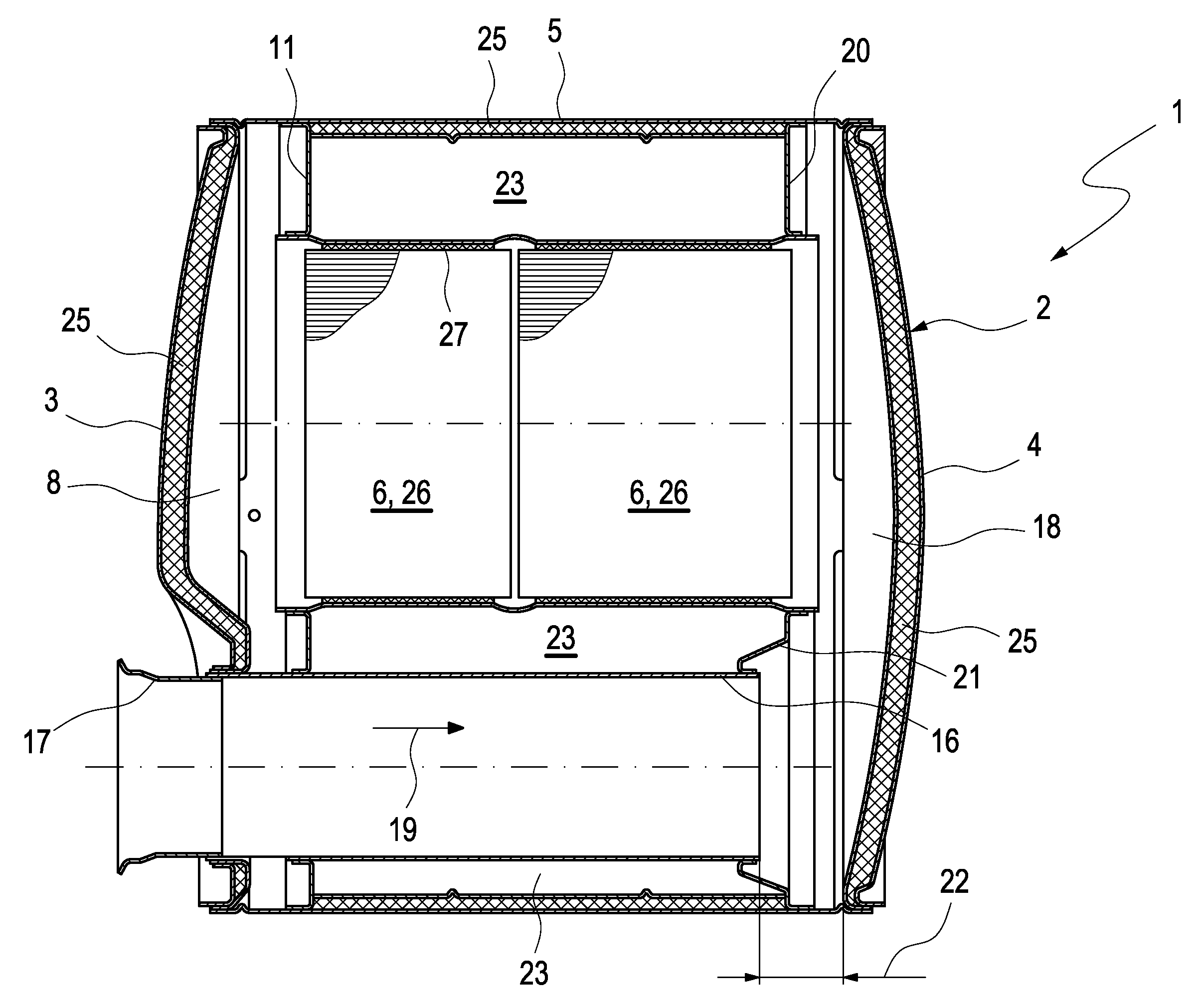
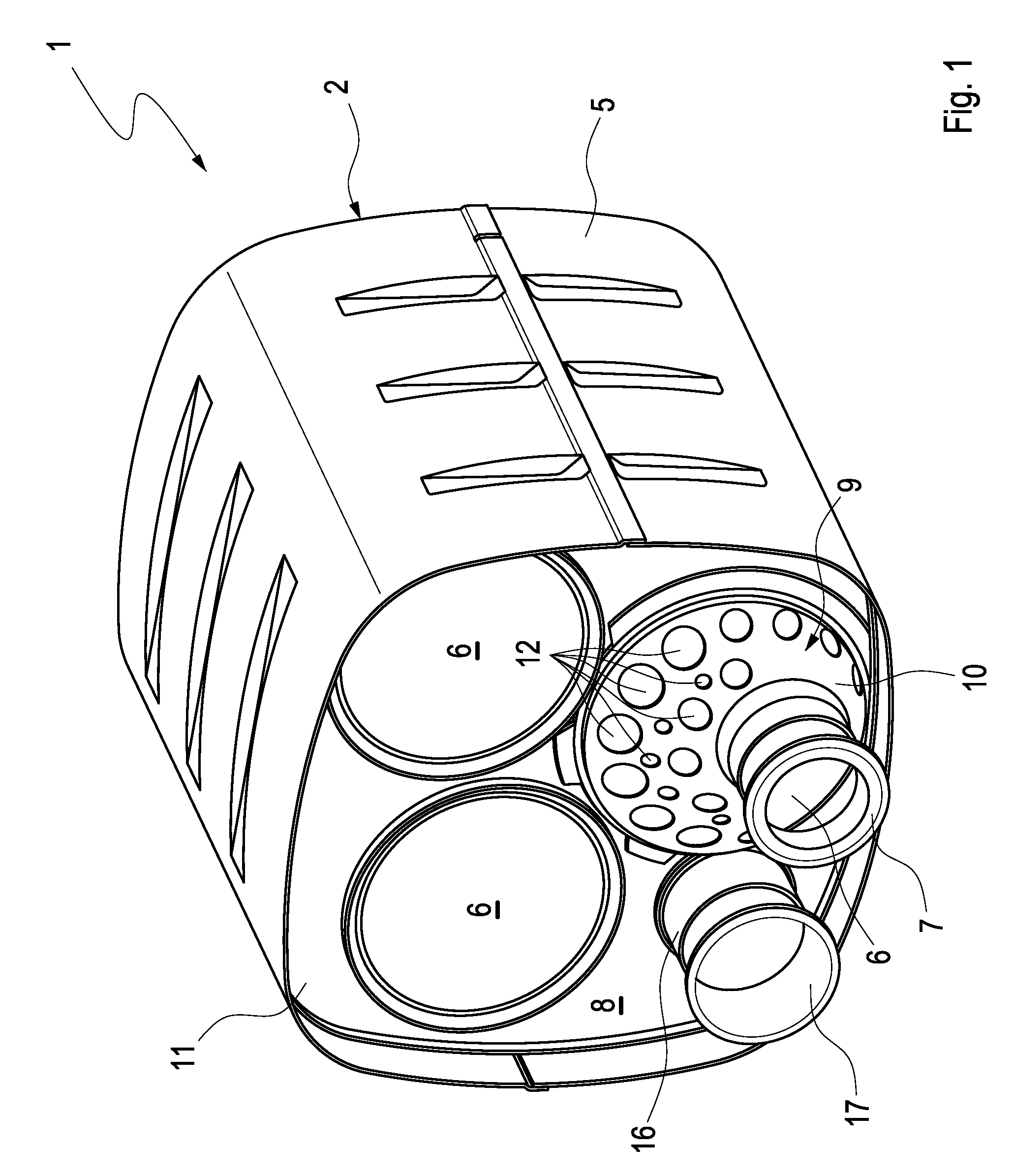
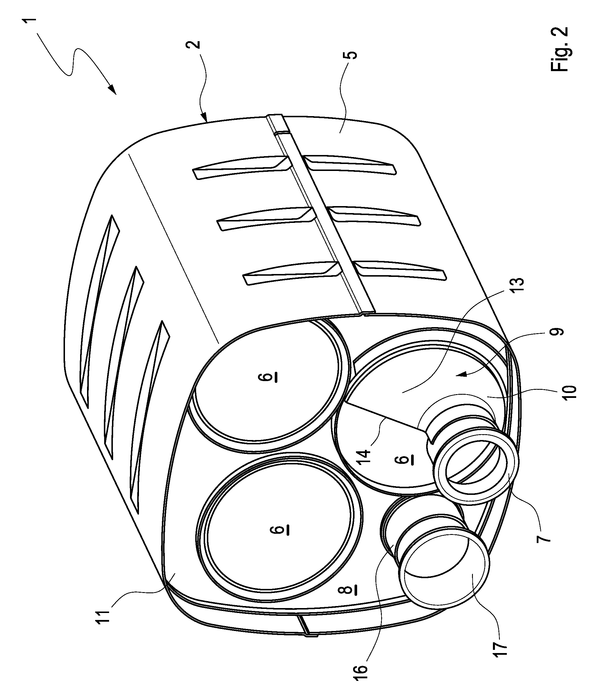
[0021]According to FIGS. 1 to 6, an exhaust gas treatment unit, especially for use in an exhaust system of a combustion engine of a motor vehicle, comprises a housing 2 that has a first side face 3, which is not shown in FIGS. 1-4 but only in FIGS. 5 and 6. Furthermore, the housing 2 has second side face 4 which again is only shown in FIGS. 5 and 6. The housing 2 further comprises a surface 5, which connects both side faces 3 and 4 together and encloses an internal space of the housing, which is not described in any more detail.

[0022]The exhaust gas treatment unit has a plurality of exhaust gas treatment elements 6. These are arranged parallel in the housing 2, such that a parallel flow through the elements can exist. As an example, three of such exhaust gas treatment elements 6 are shown. There may be more or less elements, however there should be at least two exhaust gas treatment elements 6. The housing 2 is provided with an outlet nozzle, which penetrates through the first side ...


PUM


Abstract

The present invention relates to an exhaust gas treatment unit for an exhaust system of a combustion engine, in particular of a motor vehicle, includes a housing, a plurality of exhaust gas treatment elements, which are arranged in the housing and through which a parallel flow is possible. The unit further includes an outlet nozzle, which penetrates a side face of the housing, and an outlet space disposed in the housing, whereby the outlet of at least one of the exhaust gas treatment elements opens into the outlet space. The rigidity and / or effectiveness of the exhaust gas treatment unit can be improved by means of a funnel body disposed in the outlet space, and comprising a funnel surface which is permeable to exhaust gas. The funnel body connects an outlet end of one of the exhaust gas treatment elements with the outlet nozzle.

Description

CROSS-REFERENCE TO RELATED PATENT APPLICATIONS[0001]This patent application claims the benefit of co-pending German Patent Application No. DE 102008022081.7, filed May 5, 2008, the entire teachings and disclosure of which are incorporated herein by reference thereto.FIELD OF THE INVENTION[0002]The present invention relates to an exhaust gas treatment unit for an exhaust system of a combustion engine, especially of a motor vehicle.BACKGROUND OF THE INVENTION[0003]Exhaust gas treatment units comprise a plurality of exhaust gas treatment elements, which are arranged in a housing and through which a parallel flow is possible. These exhaust gas treatment elements can open out into a common outlet space. An outlet tube or outlet nozzle leads from the outlet space out of the housing. A number of problems can however result from this. Firstly, the tube must be relatively firmly supported at the housing. Secondly, the flow from the various exhaust gas treatment elements towards the outlet tu...

Claims


Application Information

Patent Timeline
Patent Type & Authority Applications(United States)
IPC IPC(8): F01N3/035F01N7/00F01N3/10F01N13/08
CPCF01N3/0335F01N13/017Y02T10/20F01N3/2885Y02T10/12Y02A50/20
Inventor WERNI, MARCUSSAUER, ANDREAS
Owner PUREM GMBH
Why Eureka
Try Eureka