Supercharge Your Innovation With Domain-Expert AI Agents!

Parallel type injection moulding method and injection moulding machine thereof

A parallel type, injection molding machine technology, applied in coating and other directions, can solve the problems of short molding cycle of pressure-holding control accuracy, high price of large-scale injection molding machines, low pressure-holding control precision, etc. The effect of high pressure control accuracy

Inactive Publication Date: 2008-12-24
UNION PLASTIC HANGZHOU MACHINERY +1
View PDF0 Cites 8 Cited by
  • Summary
  • Abstract
  • Description
  • Claims
  • Application Information

AI Technical Summary

Problems solved by technology

[0003] The present invention solves the shortcomings of existing large-scale injection molding machines, such as high price, long molding cycle, high energy consumption, low precision of pressure-holding control, and poor adaptability, and provides a machine with low cost, good adaptability, low energy consumption, and high precision of pressure-holding control. , Injection molding method with short molding cycle and its equipment

Method used


Image

  • Parallel type injection moulding method and injection moulding machine thereof
  • Parallel type injection moulding method and injection moulding machine thereof
  • Parallel type injection moulding method and injection moulding machine thereof

Examples


Embodiment 1

[0020] Referring to the attached picture:

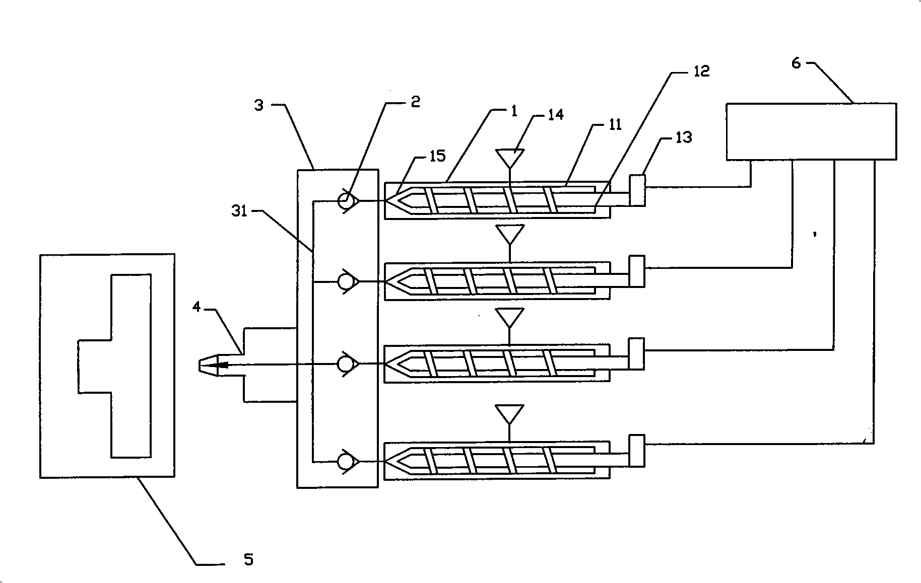
[0021] The parallel injection molding method described in the present invention adopts injection molding unit 1 for mold injection molding. The injection injection unit 1 includes a material tube 11 and a screw 12. In addition to the known steps, two or more injection injection units 1 After the one-way valve 2 is connected in parallel, it is injected into the mold through a nozzle 4. Each of the above-mentioned feeding injection units 1 injects sequentially, and injects the mold continuously.

[0022] It is also possible to make each feeding injection unit 1 inject sequentially and then repeatedly inject. In this way, the grades of the barrel 11 and the screw 12 can be further reduced, reducing equipment investment and energy consumption.

Embodiment 2

[0024] Referring to the attached picture:

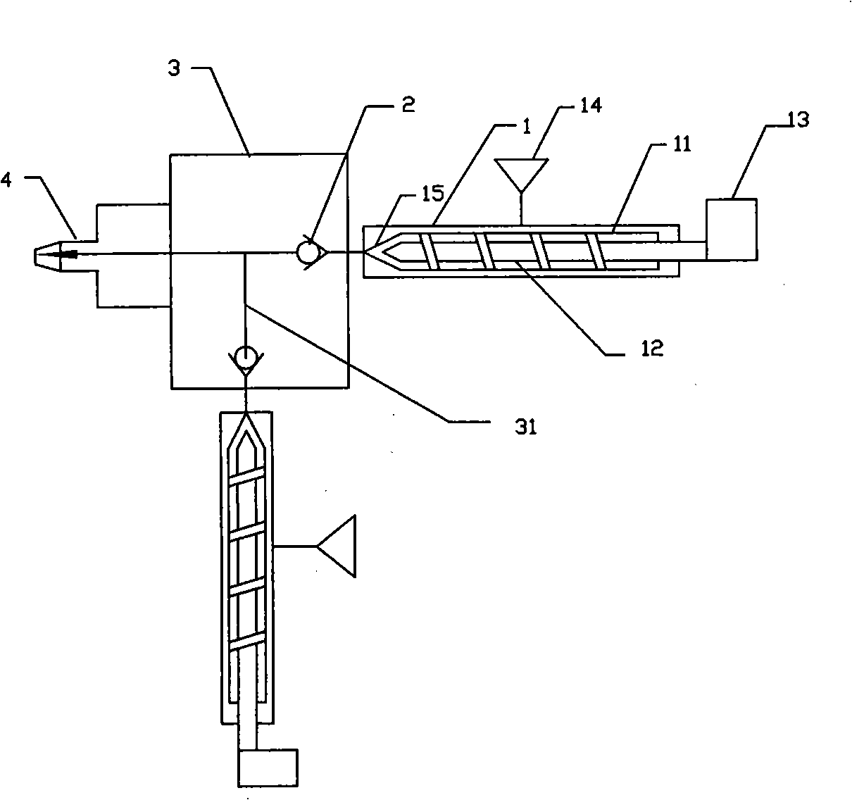
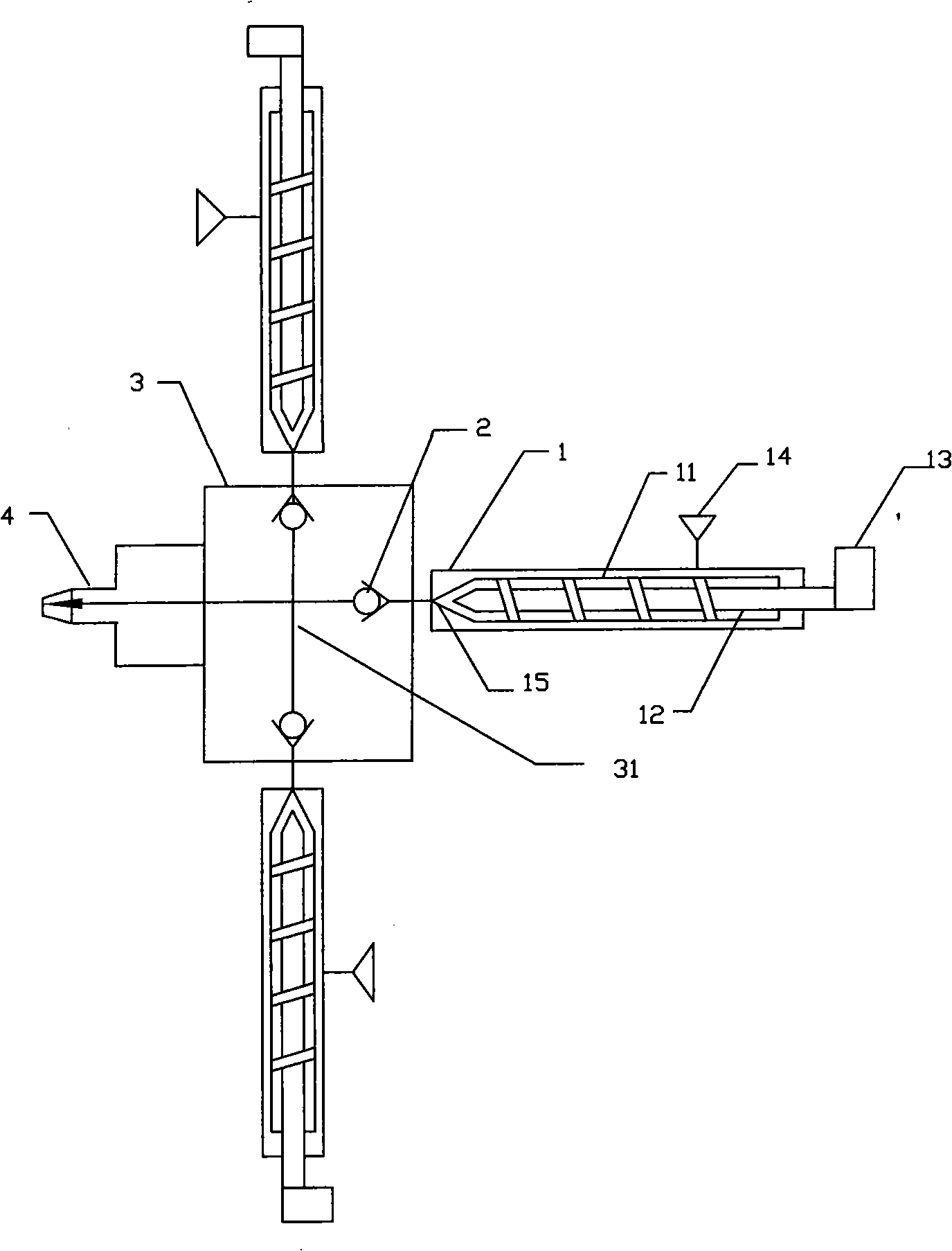
[0025] This embodiment relates to an injection molding machine using the parallel injection molding method described in the present invention, including a mold clamping mechanism 5, and a feeding injection unit 1 for injecting and feeding materials to the mold. The feeding injection unit 1 includes a material pipe 11, a screw 12, Screw driving mechanism 13, feeding mechanism 14, the described feeding injection unit 1 is equipped with a heating mechanism and heat preservation mechanism, the nozzle 4 of the described feeding injection unit 1 corresponds to the mould, and the described nozzle 4 is connected in parallel with more than two The feed injection unit 1, the injection port 15 of the material pipe 11 of each feed injection unit 1 communicates with the nozzle 4 through the one-way valve 2.

[0026] The injection ports 15 of each feed injection unit 1 are respectively connected to the interface of an interface template 3 , and th...


PUM


Abstract

The invention discloses a parallel injection method. More than two feeding ejaculation units are connected in parallel through a check valve and ejaculate to a die through a nozzle. A special equipment injector comprises a locking mechanism and the feeding ejaculation units for the feeding ejaculation to the die. The feeding ejaculation unit comprises a charge pipe, a screw, a screw driving mechanism and a feeding mechanism. The feeding ejaculation unit is provided with a heating mechanism and an insulation mechanism. The nozzle of the feeding ejaculation units faces towards the die. The nozzle is connected with more than two feeding ejaculation units in parallel. The ejaculation port of every feeding ejaculation unit is communicated with the nozzle through the check valve. The parallel injection method has the advantages of low cost, good adaptability, low consumption, high pressure retaining control precision and short molding period.

Description

technical field [0001] The invention relates to an injection molding method and an injection molding machine. Background technique [0002] Conventional injection molding machines consist of a single screw and a single injection tube. If it is necessary to manufacture large plastic parts, a large injection molding machine is required. For example, at present, the pipe joints of large plastic pipes weigh 70-120 kg, and practitioners need to purchase large injection molding machines to meet the production requirements. Large-scale injection molding machines are huge, expensive, and have a long payback period. Second, large-scale injection molding machines have a large amount of molten plastic in a single mold, and the molding cycle is very long, generally taking 10-30 minutes, and the production efficiency is low. Third, in order to ensure the size of the product, the material tube needs to maintain pressure after injection. The pressure is generally maintained by driving th...

Claims


Application Information

Patent Timeline
IPC IPC(8): B29C45/00B29C45/03B29C45/22B29C45/76
CPCB29C45/13
Inventor 陈文魁
Owner UNION PLASTIC HANGZHOU MACHINERY
Features
  • R&D
  • Intellectual Property
  • Life Sciences
  • Materials
  • Tech Scout
  • Unparalleled Data Quality
  • Higher Quality Content
  • 60% Fewer Hallucinations
Learn More