Method for dynamically measuring guide rail linearity

A technology of dynamic measurement and straightness, applied in the direction of measuring devices, instruments, optical devices, etc., can solve the problems of inability to dynamically and continuously measure the straightness of guide rails, large visual errors, visual fatigue, etc., and achieve dynamic continuous measurement and data processing Intuitive and reliable results

Inactive Publication Date: 2010-06-02
CHANGCHUN INST OF OPTICS FINE MECHANICS & PHYSICS CHINESE ACAD OF SCI
View PDF5 Cites 0 Cited by
  • Summary
  • Abstract
  • Description
  • Claims
  • Application Information

AI Technical Summary

Problems solved by technology

[0003] In the past, the detection of the straightness of the guide rail on some photoelectric instruments relied on the eyes to judge the change of the clamping distance in the eyepiece of the autocollimator to judge the straightness of the guide rail. Long-term observation caused visual fatigue and produced a large visual error, and it is impossible to dynamically and continuously measure the straightness of the guide rail

Method used


Image

  • Method for dynamically measuring guide rail linearity
  • Method for dynamically measuring guide rail linearity
  • Method for dynamically measuring guide rail linearity

Examples


Embodiment Construction

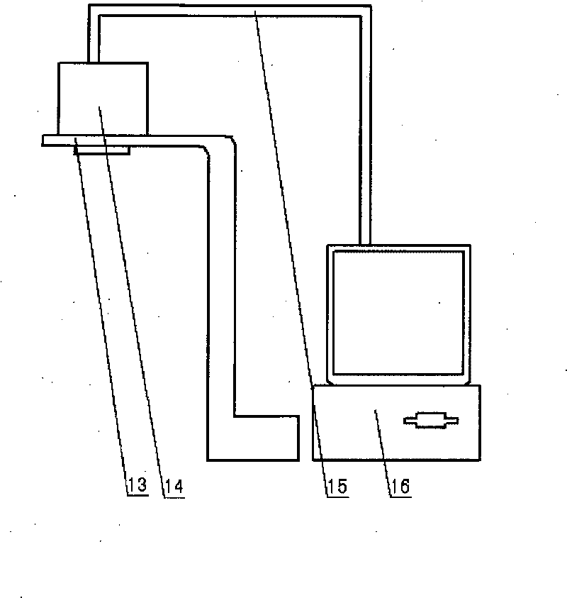
[0017] The instrument and equipment that the inventive method adopts presses Figure 4 The position shown is placed and docked on the optical measurement platform 1, and each step of the method is executed according to the five steps set in the technical plan, wherein the optical measurement platform 1 used in the first step adopts an isolated and stable platform with a foundation, and the platform’s The working surface is a 1000cm×800cm rectangular platform.

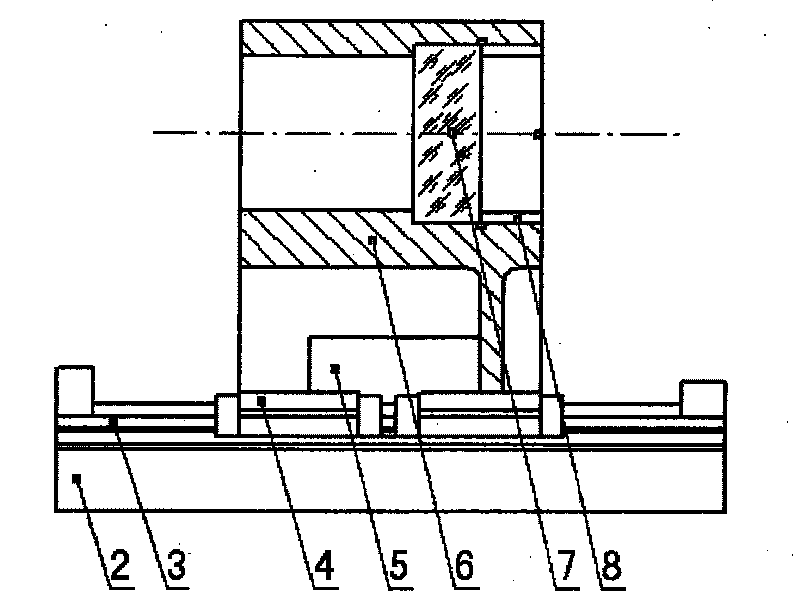
[0018] In the second step, the integrated part composed of the base 2 and the guide rail 3 is placed on the left half of the optical measurement platform 1, the slider 4 in the component to be tested is installed on the guide rail 3, and the screw rod of the linear motor assembly 5 passes through two The end seat is fixed on the base 2, the linear motor is fixed on the mirror frame, and the mirror frame is fixed on the slider. The linear motor assembly 5 drives the mirror frame and the slider 4 to move linearly along th...


PUM


Abstract

The invention discloses a dynamic measuring method of guide rail straightness, belongs to the methods that are related to the technical field of photoelectric measurement, aims at solving the technical problem of providing a method that dynamically measures guide rail straightness, and adopts the following technical proposal: (1) an optical measuring table is prepared; (2) a component to be measured is placed on the left half part of the table, and a linear motion actuator component drives a plane mirror that is arranged on a mirror shelf to move along a guide rail synchronously with a slide block; (3) an autocollimator is placed on the right side of the component to be measured and is butt-jointed with the component to be measured, the plane mirror reflects parallel light that is emittedfrom the autocollimator into the view field of a light tube ocular glass; (4) a signal receiving and data processing system is placed on the right side of the autocollimator, and the focal plane of the light tube ocular glass is led to be coincided with the receiving plane of a CCD receiver; (5) the linear motion actuator component drives the slide block and the plane mirror to move in a measuringrange along the guide rail, and a microprocessor is used for determining the change of the relative displacement of a reticle that is reflected by the plane mirror, thus realizing the measurement ofguide rail straightness.

Description

technical field [0001] The invention belongs to a method for dynamically measuring the straightness of a guide rail and relates to the technical field of photoelectric measurement. Background technique [0002] With the continuous development of scientific and technological progress, the precision requirements for some optical precision instruments are constantly increasing. Some optical instruments need to move linearly on the guide rail during work. The straightness of the guide rail directly affects the accuracy of optical instruments. Therefore, it is necessary to detect the straightness of the guide rail installed on the large photoelectric equipment. [0003] In the past, the detection of the straightness of the guide rail on some photoelectric instruments relied on the eyes to judge the change of the clamping distance in the eyepiece of the autocollimator to judge the straightness of the guide rail. Long-term observation caused visual fatigue and produced a large visu...

Claims


Application Information

Patent Timeline
Patent Type & Authority Patents(China)
IPC IPC(8): G01B11/27
Inventor 刘大禹高飞
Owner CHANGCHUN INST OF OPTICS FINE MECHANICS & PHYSICS CHINESE ACAD OF SCI
Why Eureka
Try Eureka