3D ultrasonographic device

An ultrasonic inspection and ultrasonic technology, which is applied in the analysis of solids using sonic/ultrasonic/infrasonic waves, material analysis using sonic/ultrasonic/infrasonic waves, instruments, etc., can solve difficult problems, decreased detection performance, and 3D imaging processing cannot be correct and smooth. issues such as

Inactive Publication Date: 2008-12-24
KK TOSHIBA
View PDF1 Cites 10 Cited by
  • Summary
  • Abstract
  • Description
  • Claims
  • Application Information

AI Technical Summary

Problems solved by technology

[0010] 1. Since the internal inspection of the inspection object is performed by observing the ultrasonic image formed by imaging processing, it is difficult to objectively and quantitatively inspect the state of the welded part and the state of the welding defect with high accuracy
[0011] 2. It is difficult to quantitatively and accurately automatically determine the presence or absence of abnormalities from the ultrasonic image obtained by imaging the inner side of the inspection object, indicating the state of the welded part and the state of the welded defect.
[0016] In addition, when the surface of the inspection object is uneven, it is difficult to make the mating shoe material come into close contact with the inspection object by merely filling the gap with a couplant
[0017] In the ultrasonic inspection equipment, when there is air bubble between the ultrasonic sensor and the inspection object, and thus there is a gap between them, it is difficult for the ultrasonic waves emitted from the ultrasonic sensor to enter the inspection object smoothly, and it is also difficult to receive the reflected echo smoothly. , so neither the ultrasonic wave nor the reflected echo can propagate normally, resulting in the problem that the detection performance is degraded, and at the same time, the three-dimensional imaging processing of the inner side of the inspection object cannot be performed correctly and smoothly.

Method used


Image

  • 3D ultrasonographic device
  • 3D ultrasonographic device
  • 3D ultrasonographic device

Examples


Embodiment Construction

[0131] Embodiments of the three-dimensional ultrasonic inspection apparatus in the present invention will be described below with reference to the drawings.

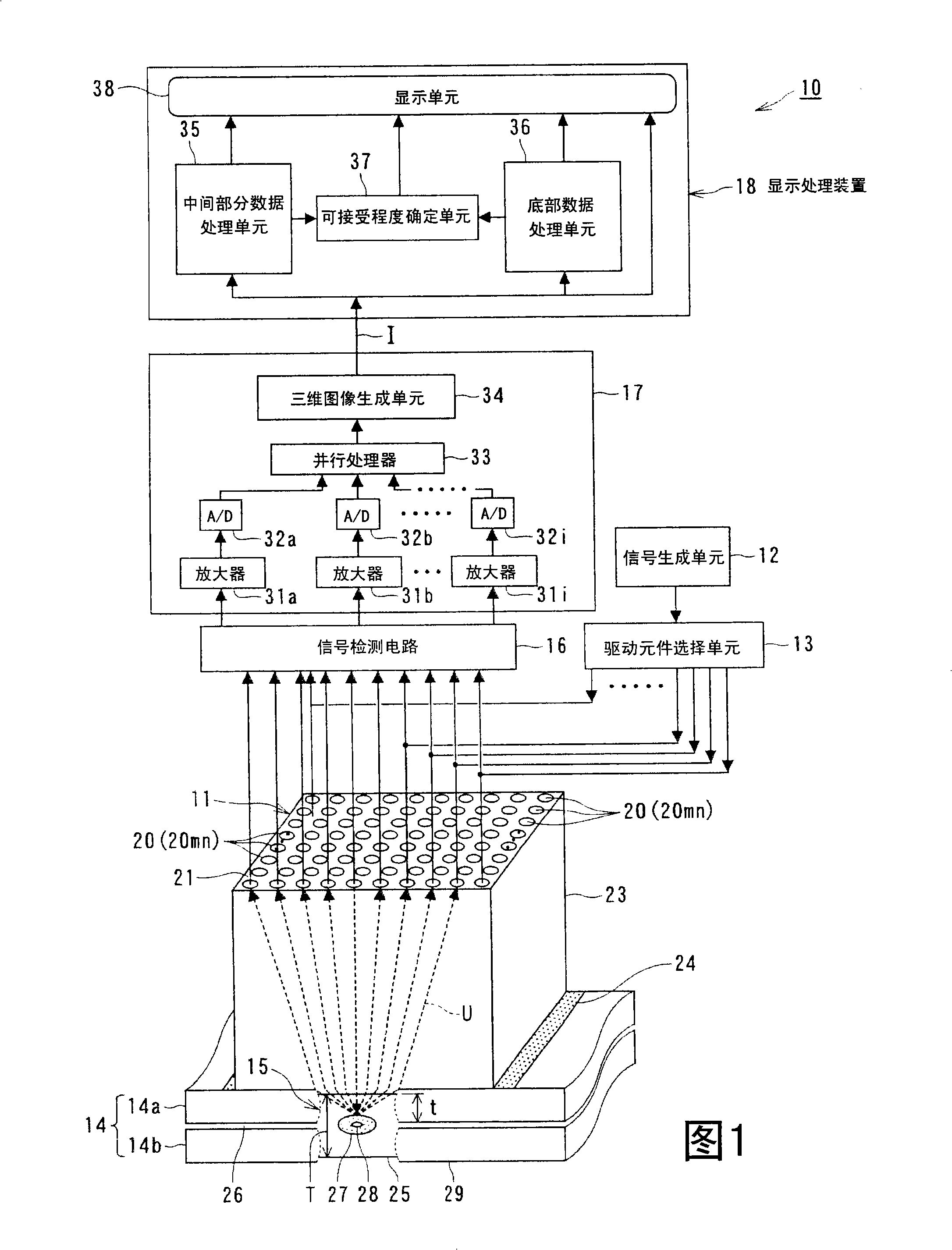
[0132] Fig. 1 is a block diagram illustrating an embodiment of a three-dimensional ultrasonic inspection apparatus in the present invention.

[0133] The three-dimensional ultrasonic inspection apparatus 10 includes: a sensing device 100 for ultrasonic inspection (details thereof will be described below), including a transducer 11 as an ultrasonic sensor that converts ultrasonic vibration into an electrical signal, and an electrical signal The signal is converted into ultrasonic vibrations, and transmits and receives ultrasonic waves with a desired frequency; the signal generation unit 12 is used to generate a drive signal to drive the ultrasonic transducer 11; the drive element selection unit 13 is used to select the signal generation unit 12 The drive signal selectively drives the piezoelectric vibrator of the ultrason...


PUM


Abstract

A 3D ultrasonographic device includes: an ultrasonographic sensor having an ultrasonic transducer having a plurality of piezoelectric vibrators arranged in a matrix or array shape; a drive element selection unit for selecting an oscillation piezoelectric vibrator from the ultrasonic transducer; a signal detection circuit for receiving a reflection echo from a junction portion of an inspection object by the oscillated ultrasonic wave and detecting electric signal; a signal processing unit for processing the electric signal detected and correlating it to the mesh in the 3D image area of the inspection object, thereby generating 3D image data; and a display processing device for detecting the size / position of the molten hardened portion and the position / size of a welding defect portion from the intensity distribution of the 3D image date generated by the signal processing unit and displaying the detection result and the 3D image data from the signal processing unit.

Description

[0001] This application is a divisional application filed on April 25, 2005, with the application number "200580021267.8" and the name "three-dimensional ultrasonic inspection equipment". technical field [0002] The present invention relates to a three-dimensional ultrasonic inspection apparatus for non-destructively inspecting the internal structure of an inspection object, the state of a joint region, and a defect state using ultrasonic waves, and more particularly, to a three-dimensional ultrasonic inspection apparatus including a sensing device for ultrasonic inspection , such a three-dimensional ultrasonic inspection apparatus is used as an ultrasonic imaging apparatus that three-dimensionally visualizes the state of a welded portion of an inspection object and the state of a welding defect. Background technique [0003] An example of a technique for nondestructive inspection of the state of welded portions and the state of welded defects in joint regions between plate-...

Claims


Application Information

Patent Timeline
Patent Type & Authority Applications(China)
IPC IPC(8): G01N29/11G01N29/06G01N29/44G01N29/04G01N29/22
CPCG01N29/0609G01N2291/048
Inventor 桧山和夫池田贤弘阿部素久唐泽博一片山雅弘
Owner KK TOSHIBA
Why Eureka
Try Eureka