
Three-dimensional ultrasonic inspection device

Through three-dimensional ultrasonic inspection equipment, matrix or array piezoelectric vibrators and signal processing technology are used to solve the problem of difficulty in accurately inspecting welding parts with two-dimensional equipment, achieving fast and accurate three-dimensional welding defect detection, simplifying operations, and improving Detection performance.

Active Publication Date: 2009-09-30
KK TOSHIBA
View PDF6 Cites 12 Cited by
  • Summary
  • Abstract
  • Description
  • Claims
  • Application Information

AI Technical Summary

Problems solved by technology

[0009] 1. Since the internal inspection of the inspection object is performed by observing the ultrasonic image formed by imaging processing, it is difficult to objectively and quantitatively inspect the state of the welded part and the state of the welding defect with high accuracy
[0010] 2. It is difficult to quantitatively and accurately automatically determine the presence or absence of abnormalities from the ultrasonic image obtained by imaging the inner side of the inspection object, indicating the state of the welded part and the state of the welded defect.
[0015] In addition, when the surface of the inspection object is uneven, it is difficult to make the mating shoe material come into close contact with the inspection object by merely filling the gap with a couplant
[0016] In the ultrasonic inspection equipment, when there is air bubble between the ultrasonic sensor and the inspection object, and thus there is a gap between them, it is difficult for the ultrasonic waves emitted from the ultrasonic sensor to enter the inspection object smoothly, and it is also difficult to receive the reflected echo smoothly. , so neither the ultrasonic wave nor the reflected echo can propagate normally, resulting in the problem that the detection performance is degraded, and at the same time, the three-dimensional imaging processing of the inner side of the inspection object cannot be performed correctly and smoothly.

Method used


Image

  • Three-dimensional ultrasonic inspection device
  • Three-dimensional ultrasonic inspection device
  • Three-dimensional ultrasonic inspection device

Examples


Embodiment Construction

[0130] Embodiments of the three-dimensional ultrasonic inspection apparatus in the present invention will be described below with reference to the drawings.

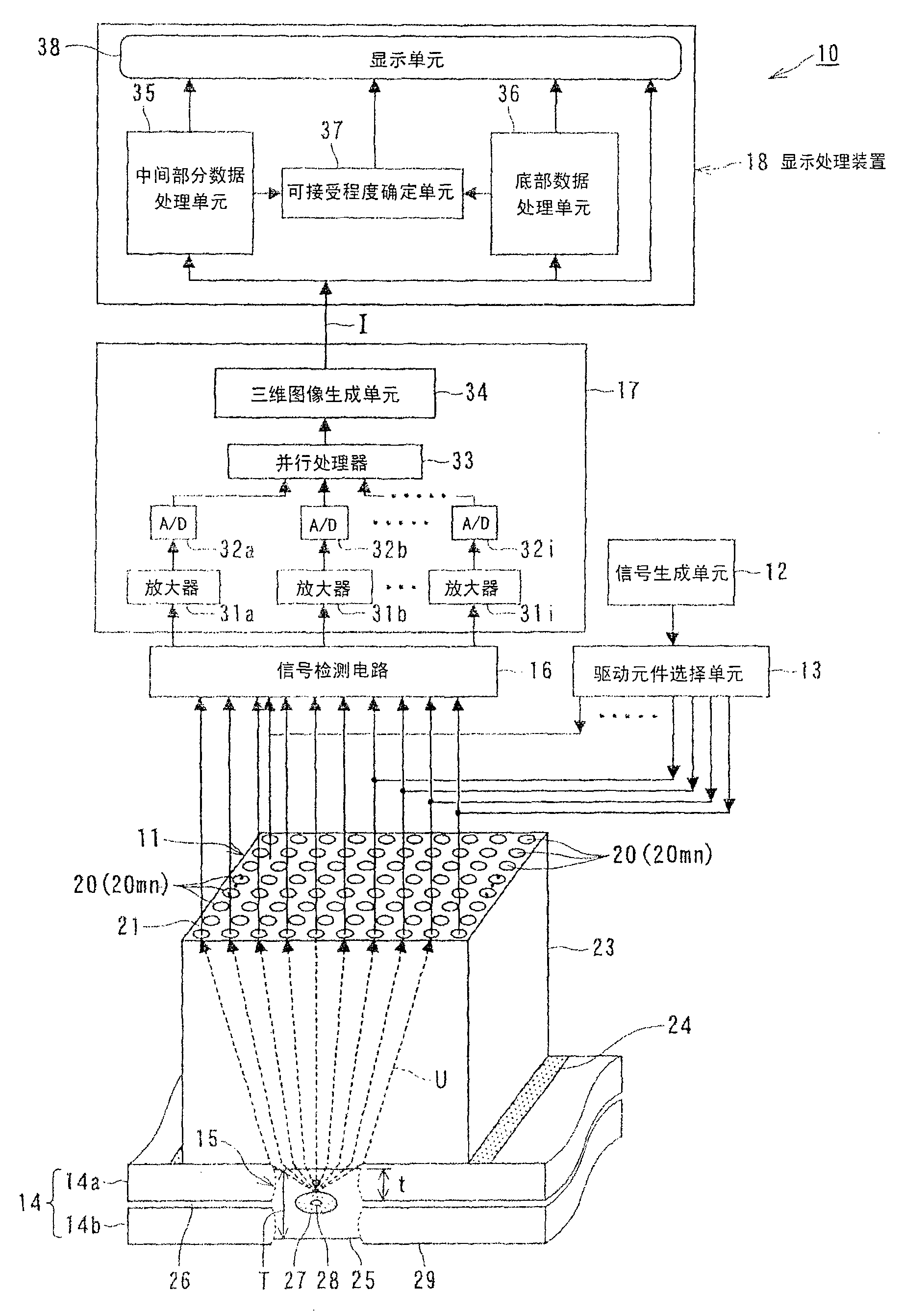
[0131] figure 1 is a structural diagram illustrating an embodiment of the three-dimensional ultrasonic inspection apparatus in the present invention.

[0132] The three-dimensional ultrasonic inspection apparatus 10 includes: a sensing device 100 for ultrasonic inspection (details thereof will be described below), including a transducer 11 as an ultrasonic sensor that converts ultrasonic vibration into an electrical signal, and an electrical signal The signal is converted into ultrasonic vibrations, and transmits and receives ultrasonic waves with a desired frequency; the signal generation unit 12 is used to generate a drive signal to drive the ultrasonic transducer 11; the drive element selection unit 13 is used to select the signal generation unit 12 The drive signal selectively drives the piezoelectric vibrator of th...


PUM


Abstract

A three-dimensional ultrasonic inspection device includes: a sensing device for ultrasonic inspection, including an ultrasonic transducer as a transducer, wherein a plurality of piezoelectric vibrators are placed in a matrix or an array; a drive element selection unit for The piezoelectric vibrator is selected and driven in the transducer to generate ultrasonic waves; the signal detection circuit is used to detect the electrical signal of the reflected echo by receiving the reflected echo from the bonding area; the signal processing unit is used to process the electrical signal into a signal processing to generate three-dimensional imaging data by making the electric signal correspond to mesh elements within the three-dimensional imaging region of the inspection object; and display processing means for displaying the detection result and the three-dimensional image from the signal processing unit data, while detecting the size and position of the melt-solidified portion, and the size and position of welding defects in the joint region from the intensity distribution of the three-dimensional imaging data generated by the signal processing unit.

Description

technical field [0001] The present invention relates to a three-dimensional ultrasonic inspection apparatus for non-destructively inspecting the internal structure of an inspection object, the state of a joint region, and a defect state using ultrasonic waves, and more particularly, to a three-dimensional ultrasonic inspection apparatus including a sensing device for ultrasonic inspection , such a three-dimensional ultrasonic inspection apparatus is used as an ultrasonic imaging apparatus that three-dimensionally visualizes the state of a welded portion of an inspection object and the state of a welding defect. Background technique [0002] An example of a technique for nondestructive inspection of the state of welded portions and the state of welded defects in joint regions between plate-like structures that are inspection objects is an ultrasonic testing technique. [0003] As an example of an ultrasonic inspection apparatus employing an ultrasonic testing technique, an ul...

Claims


Application Information

Patent Timeline
Patent Type & Authority Patents(China)
IPC IPC(8): G01N29/06G01N29/44G01N29/04G01N29/22
CPCG01N29/0609G01N2291/048
Inventor 桧山和夫池田贤弘阿部素久唐泽博一片山雅弘
Owner KK TOSHIBA
Learn More