Method and device for adjusting liquid crystal display contrast
A liquid crystal display and adjustment method technology, which is applied to static indicators, instruments, etc., can solve the problems of large device loss, limited contrast adjustment range, and large backlight loss, so as to reduce power loss, realize adaptive brightness adjustment, and improve The effect of dynamic contrast
- Summary
- Abstract
- Description
- Claims
- Application Information
AI Technical Summary
Problems solved by technology
Method used
Image
Examples
no. 2 example
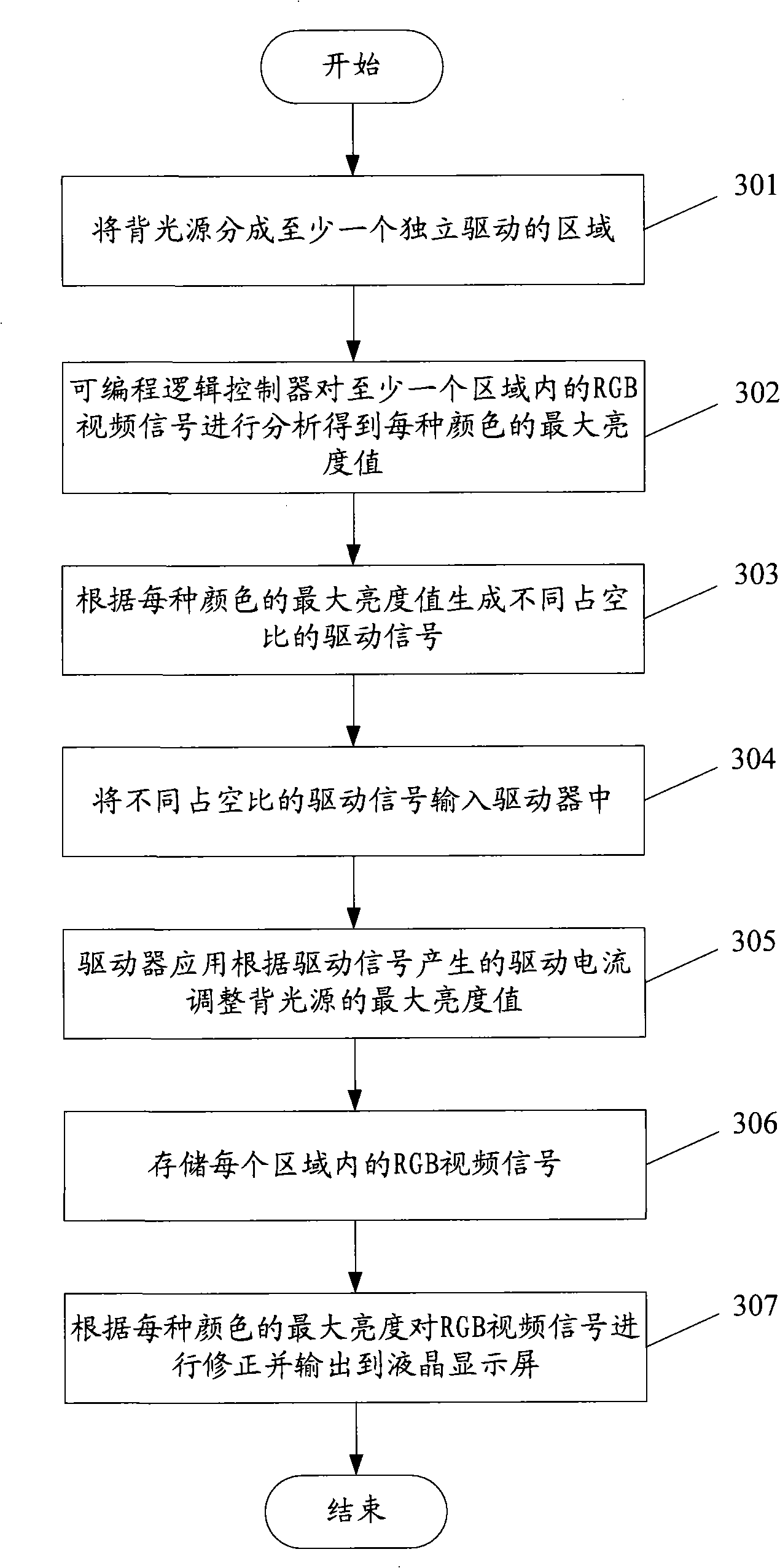
[0077] The process flow of the second embodiment of the method of the present invention is as follows image 3 As shown, this embodiment shows the process of only generating the driving signal by the programmable logic controller to adjust the contrast of the backlight source:
[0078] Step 301: Divide the backlight into at least one independently driven area.
[0079] Step 302: The programmable logic controller analyzes the RGB video signals in at least one area to obtain the maximum brightness value of each color.
[0080] Step 303: Generate driving signals with different duty ratios according to the maximum scale value of each color.
[0081] Step 304: Input driving signals with different duty ratios into the driver.
[0082] Step 305: The driver application adjusts the maximum brightness value of the backlight source according to the driving current generated by the driving signal.
[0083] Step 306: Store RGB video signals in each area.
[0084] Step 307: Correct the ...
no. 3 example
[0100] The process of the third embodiment of the method of the present invention is as follows Figure 5 As shown, this embodiment shows the process of jointly generating the driving signal by the color controller and the programmable logic controller:
[0101] Step 501: Divide the backlight into at least one independently driven area.
[0102] Step 502: The programmable logic controller analyzes the RGB video signals in at least one area to obtain the maximum brightness value of each color, and generates first driving signals with different duty ratios according to the maximum brightness value.
[0103] Step 503: The color sensor in at least one area inputs the color temperature signal obtained by monitoring the emitted light into the color controller, and the color controller generates second driving signals with different duty ratios according to the color temperature signal.
[0104] Step 504: Combine the driving signal generated by the color controller and the driving sig...
no. 4 example
[0113] The flow chart of the fourth embodiment of the method of the present invention is as follows Figure 7 As shown, this embodiment shows the flow of only the color controller generating the driving signal to adjust the contrast of the backlight source:
[0114] Step 701: Divide the backlight into at least one independently driven area.
[0115] Step 702: The color sensor in at least one area inputs the color temperature signal obtained by monitoring the outgoing light into the color controller.
[0116] Step 703: The programmable logic controller analyzes the RGB video signals in at least one area to obtain a maximum brightness value signal of each color, and inputs the maximum brightness value signal to the color controller.
[0117] Step 704: The color controller in at least one area generates driving signals with different duty ratios according to the color temperature signal and the maximum brightness value signal.
[0118] Step 705: Input driving signals with diffe...
PUM
 Abstract
Description
Claims
Application Information
 - R&D
- Intellectual Property
- Life Sciences
- Materials
- Tech Scout
- Unparalleled Data Quality
- Higher Quality Content
- 60% Fewer Hallucinations
Browse by: Latest US Patents, China's latest patents, Technical Efficacy Thesaurus, Application Domain, Technology Topic, Popular Technical Reports.
© 2025 PatSnap. All rights reserved.Legal|Privacy policy|Modern Slavery Act Transparency Statement|Sitemap|About US| Contact US: help@patsnap.com


