
Method and device for adjusting liquid crystal display contrast

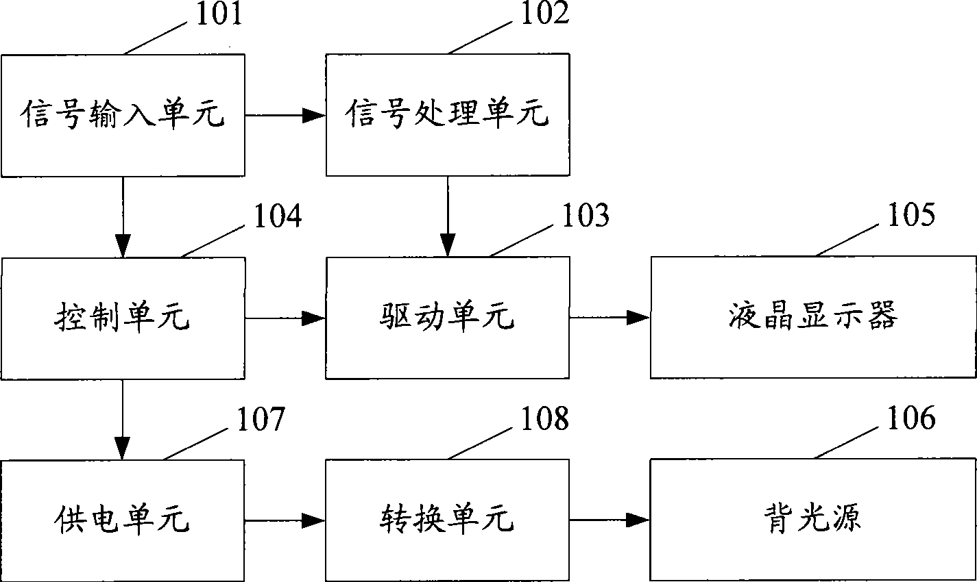
A liquid crystal display and adjustment method technology, applied to static indicators, instruments, etc., can solve the problems of limited contrast adjustment range, large device loss, large backlight loss, etc., to achieve adaptive brightness adjustment, reduce power loss, improve The effect of dynamic contrast

Active Publication Date: 2010-09-22
HISENSE VISUAL TECH CO LTD
View PDF6 Cites 0 Cited by
  • Summary
  • Abstract
  • Description
  • Claims
  • Application Information

AI Technical Summary

Problems solved by technology

[0005] The purpose of the present invention is to provide a method for adjusting the contrast of a liquid crystal display to solve the problem that the existing contrast adjustment technical scheme has a large loss of the backlight source and cannot cooperate with the backlight source to adjust the video signal, thus limiting the contrast adjustment range.
[0006] Another object of the present invention is to provide a device for adjusting the contrast of a liquid crystal display to solve the problem that the device in the prior art has a large loss and cannot adjust the video signal, thus limiting the range of contrast adjustment

Method used


Image

  • Method and device for adjusting liquid crystal display contrast
  • Method and device for adjusting liquid crystal display contrast
  • Method and device for adjusting liquid crystal display contrast

Examples


no. 2 example

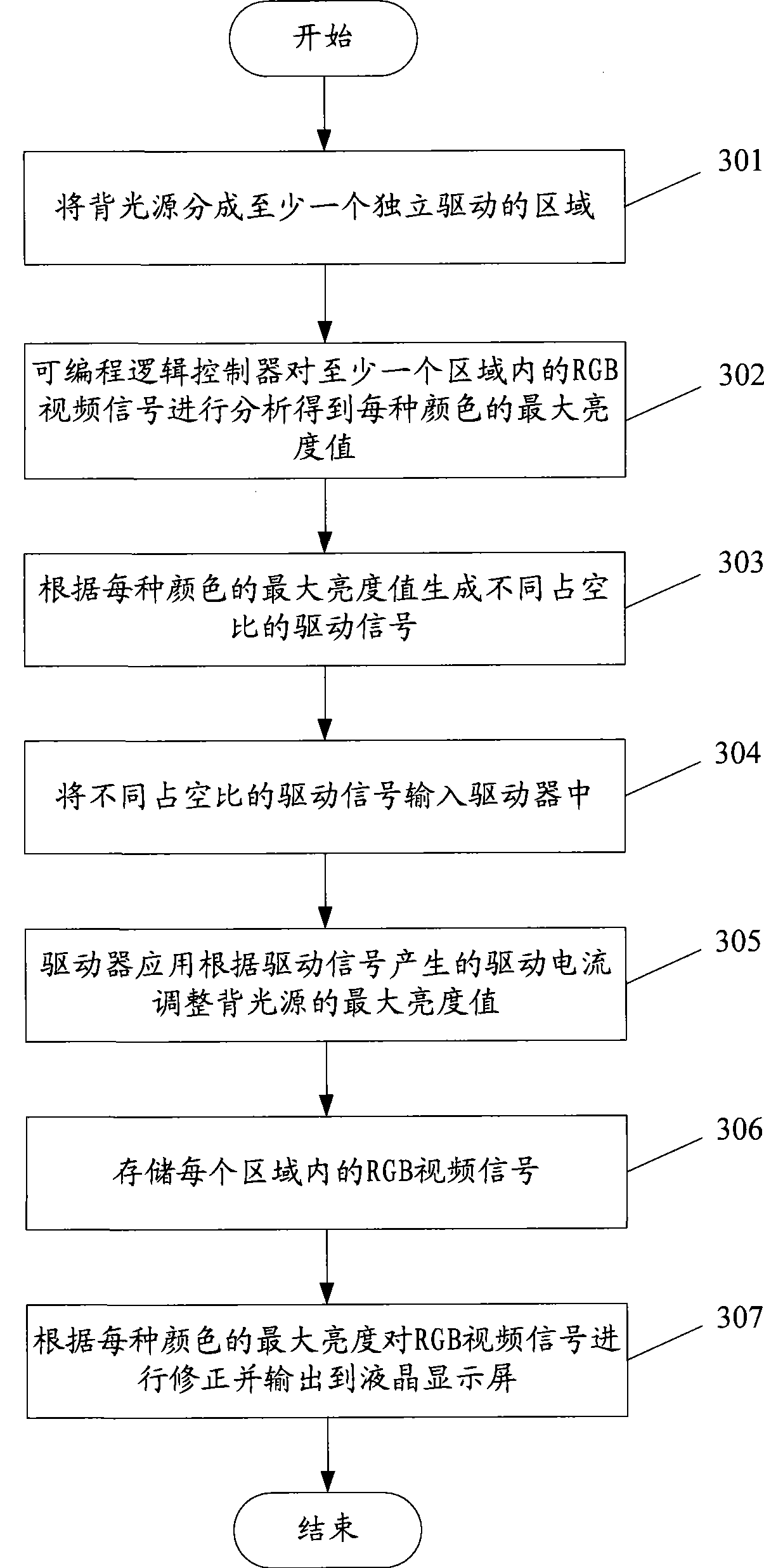
[0077] The process flow of the second embodiment of the method of the present invention is as follows image 3 As shown, this embodiment shows the process of only generating the driving signal by the programmable logic controller to adjust the contrast of the backlight source:

[0078] Step 301: Divide the backlight into at least one independently driven area.

[0079] Step 302: The programmable logic controller analyzes the RGB video signals in at least one area to obtain the maximum brightness value of each color.

[0080] Step 303: Generate driving signals with different duty ratios according to the maximum brightness value of each color.

[0081] Step 304: Input driving signals with different duty ratios into the driver.

[0082] Step 305: The driver application adjusts the maximum brightness value of the backlight source according to the driving current generated by the driving signal.

[0083] Step 306: Store RGB video signals in each area.

[0084] Step 307: Correct...

no. 3 example

[0100] The process of the third embodiment of the method of the present invention is as follows Figure 5 As shown, this embodiment shows the process of jointly generating the driving signal by the color controller and the programmable logic controller:

[0101] Step 501: Divide the backlight into at least one independently driven area.

[0102] Step 502: The programmable logic controller analyzes the RGB video signals in at least one area to obtain the maximum brightness value of each color, and generates first driving signals with different duty ratios according to the maximum brightness value.

[0103] Step 503: The color sensor in at least one area inputs the color temperature signal obtained by monitoring the emitted light into the color controller, and the color controller generates second driving signals with different duty ratios according to the color temperature signal.

[0104] Step 504: Combine the driving signal generated by the color controller and the driving sig...

no. 4 example

[0113] The flow chart of the fourth embodiment of the method of the present invention is as follows Figure 7 As shown, this embodiment shows the flow of only the color controller generating the driving signal to adjust the contrast of the backlight source:

[0114] Step 701: Divide the backlight into at least one independently driven area.

[0115] Step 702: The color sensor in at least one area inputs the color temperature signal obtained by monitoring the outgoing light into the color controller.

[0116] Step 703: The programmable logic controller analyzes the RGB video signals in at least one area to obtain a maximum brightness value signal of each color, and inputs the maximum brightness value signal to the color controller.

[0117] Step 704: The color controller in at least one area generates driving signals with different duty ratios according to the color temperature signal and the maximum brightness value signal.

[0118] Step 705: Input driving signals with diffe...


PUM


Abstract

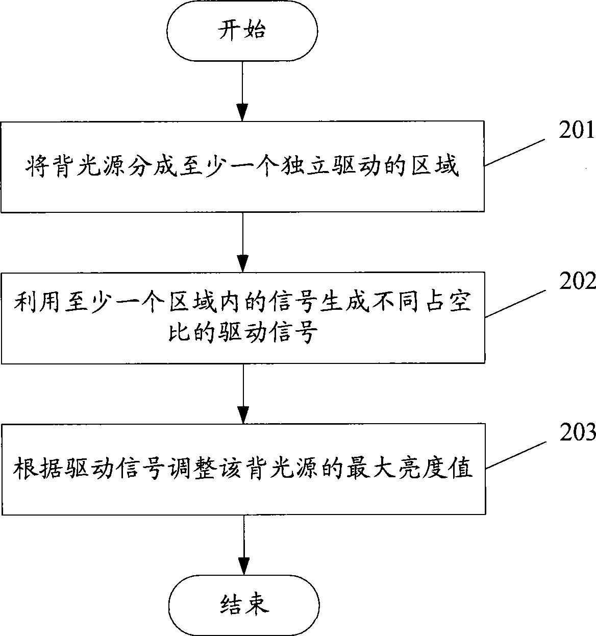
The invention discloses an adjustment method of the contrast of a liquid crystal display, and the adjustment method comprises the following steps: a backlight source is divided into at least one independent drive region; a drive signal is generated by utilizing the signal in at least one region; the maximum brightness valve of the backlight source is adjusted according to the drive signal. The invention further discloses an adjustment device of the contrast of the liquid crystal display, and the adjustment device comprises the backlight source, a signal generation unit and a drive unit. The application of the invention can adjust the brightness value of the backlight source according to the maximum brightness value of various colors of an image to be displayed by the liquid crystal display device, and the correction to a video signal is further carried out to ensure the brightness value of the displayed image not to be reduced along with the decrease of the brightness of the backlightsource, thereby reducing the power loss of the backlight source, improving the dynamic contrast ratio of the liquid crystal display and realizing the self-adaptive brightness adjustment of the backlight source of the liquid crystal display.

Description

technical field [0001] The invention relates to the field of liquid crystal display technology, in particular to a method and device for adjusting the contrast of a liquid crystal display. Background technique [0002] Most of the LCD (Liquid Crystal Display, liquid crystal display devices) such as LCD TVs and liquid crystal displays are transmissive LCDs, which cannot emit light by themselves. The brightness enables the LCD to display images normally to achieve a full color display effect. Most traditional LCDs use CCFL (Cold Cathode Fluorescent Lamp, Cold Cathode Fluorescent Lamp) as the backlight source, but with the continuous development of LED (light emitting diode, light-emitting diode) chip manufacturing technology and packaging technology, the brightness of the LED backlight source has gradually increased, and the color It has become the LCD of small portable terminals, such as mobile phones, media players, PDA (Personal Digital Assistant, personal digital assistan...

Claims


Application Information

Patent Timeline
Patent Type & Authority Patents(China)
IPC IPC(8): G02F1/133G09G3/34G09G3/36
Inventor 刘卫东张留朝乔明胜陈兴锋
Owner HISENSE VISUAL TECH CO LTD
Learn More