Unlock instant, AI-driven research and patent intelligence for your innovation.

An extraction device

An extraction device and gas technology, applied in the field of gas extraction devices, to achieve the effect of low pressure loss

Inactive Publication Date: 2008-12-24
ATKINS LTD
View PDF4 Cites 0 Cited by
  • Summary
  • Abstract
  • Description
  • Claims
  • Application Information

AI Technical Summary

Problems solved by technology

As a result, the amount of gas flowing through the area between the nozzles will increase, causing a large amount of flow-through gas to pass through without scrubbing.

Method used


Image

  • An extraction device
  • An extraction device
  • An extraction device

Examples


Embodiment Construction

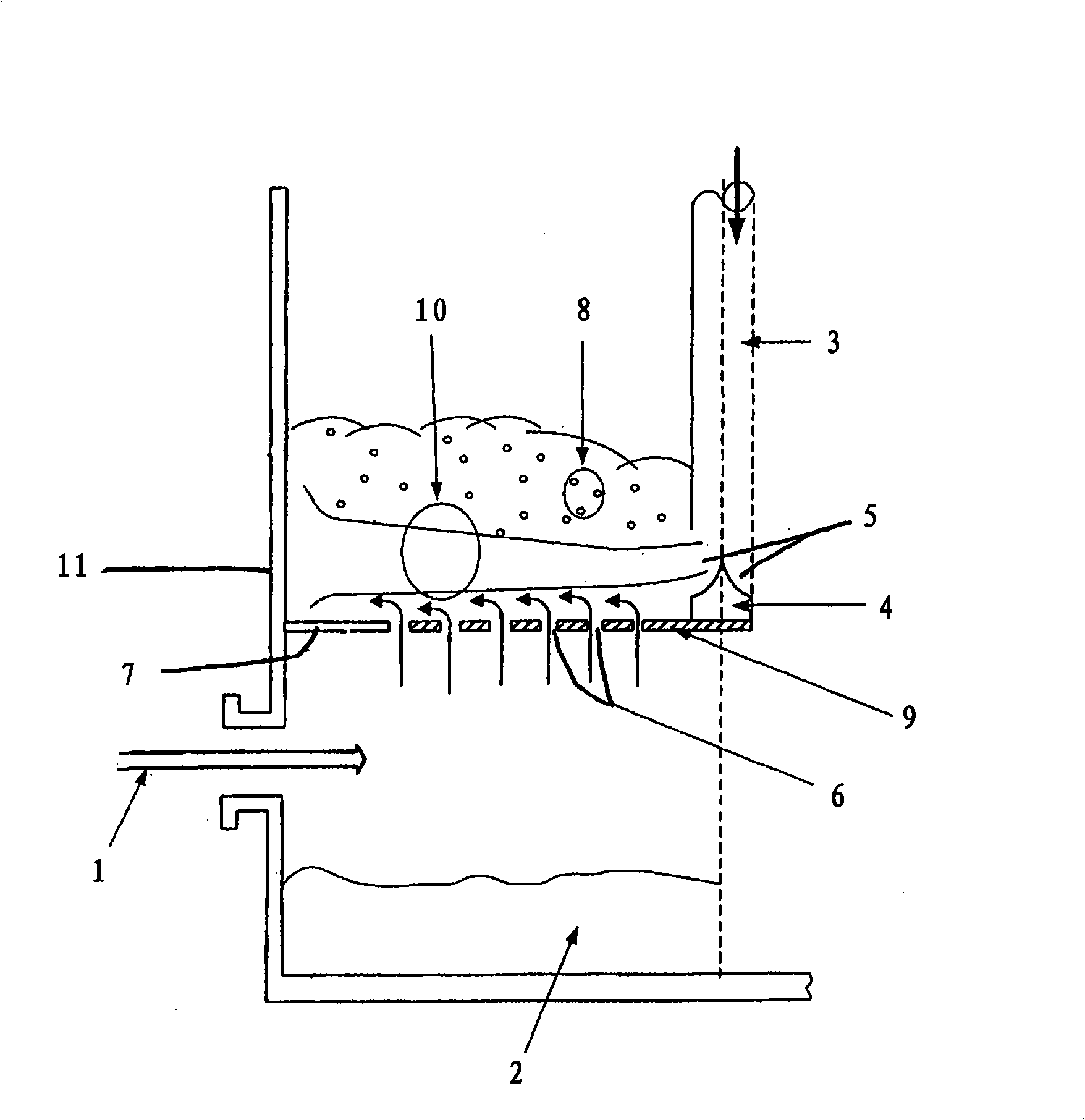
[0036] figure 1 The extraction device shown comprises a gas flow inlet 1 which opens into an area immediately below and adjacent to a diffuser plate 9, a part of which forms a sump 2 provided for the liquid flow (which will be described below). discuss). The liquid inlet comprises a central pipe 3 pointing downwards immediately above the diffuser plate 9 with a curvilinear conical choke 4 . The opening of the central tube 3 and the choke 4 form a slit 5, the curvilinear conical choke 4 redirecting the liquid flow through the slit 5 to flow horizontally across the diffuser plate. In the illustrated embodiment, the slit 5 forms a circumferential inlet for the liquid, with a height of between 5mm and 20mm, depending on the pressure and volumetric flow rate of the liquid required to form a continuous liquid flow surface on the diffuser plate.

[0037] The diffuser plate 9 has a plurality of openings or holes 6 through which the air flow can flow. In the illustrated embodiment, ...


PUM


Abstract

An extraction device, preferably a scrubbing device, for a gas comprising a diffuser for transmitting a gas through a diffusing zone of the diffuser and means for jetting a stream of liquid over the whole of the diffusing zone such that the gas is entrained by the stream of liquid. A method is also provided, including jetting a stream of liquid over the whole of a diffusing zone of a diffuser and transmitting a gas through the diffusing zone into contact with the steam of liquid.

Description

technical field [0001] The invention relates to an extraction device for a gas, such as a gas-liquid contact device for transferring mass, heat and / or momentum between a gas and a liquid, and in particular, the invention relates to a gas scrubber A device for removing water-soluble gases from a gas mixture. Background technique [0002] The requirements for such devices are the same in many industrial sectors, such as the chemical industry or the power generation industry, where the devices performing this function are often referred to as gas scrubbers. These devices exhibit varying performance depending on their design and the application in which they are placed. [0003] In industry, the need to remove certain components from exhaust or process gas streams stems from the fact that these components present a potential risk of causing damage to the environment or creating a toxic nuisance. For example, sulfur compounds contained in hydrocarbon fuels result in the emissio...

Claims


Application Information

Patent Timeline
Patent Type & Authority Applications(China)
IPC IPC(8): B01D53/50B01D53/74B01D53/75B01D53/79B01D53/18
CPCB01D53/18B01D53/185B01D53/504B01D53/507B01D53/78B01D53/92
Inventor 约翰·D·扬史蒂文·吉勒姆彼得·J·伍德伯恩
Owner ATKINS LTD
Features
  • R&D
  • Intellectual Property
  • Life Sciences
  • Materials
  • Tech Scout
  • Unparalleled Data Quality
  • Higher Quality Content
  • 60% Fewer Hallucinations
Learn More