Liquid crystal display panel

一种液晶显示面板、液晶层的技术,应用在静态指示器、非线性光学、仪器等方向,能够解决影响液晶显示面板显示等问题

Inactive Publication Date: 2008-12-31
INNOCOM TECH (SHENZHEN) CO LTD +1
View PDF0 Cites 5 Cited by
  • Summary
  • Abstract
  • Description
  • Claims
  • Application Information

AI Technical Summary

Problems solved by technology

[0008] In order to solve the problem that the spacers in the prior art affect the display of the liquid crystal display panel, it is necessary to provide a liquid crystal display panel that prevents spacers from affecting the display effect.

Method used


Image

  • Liquid crystal display panel
  • Liquid crystal display panel
  • Liquid crystal display panel

Examples


Embodiment Construction

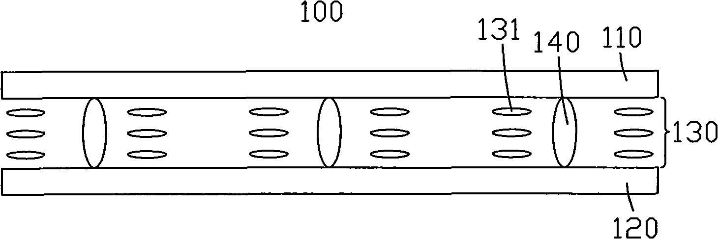
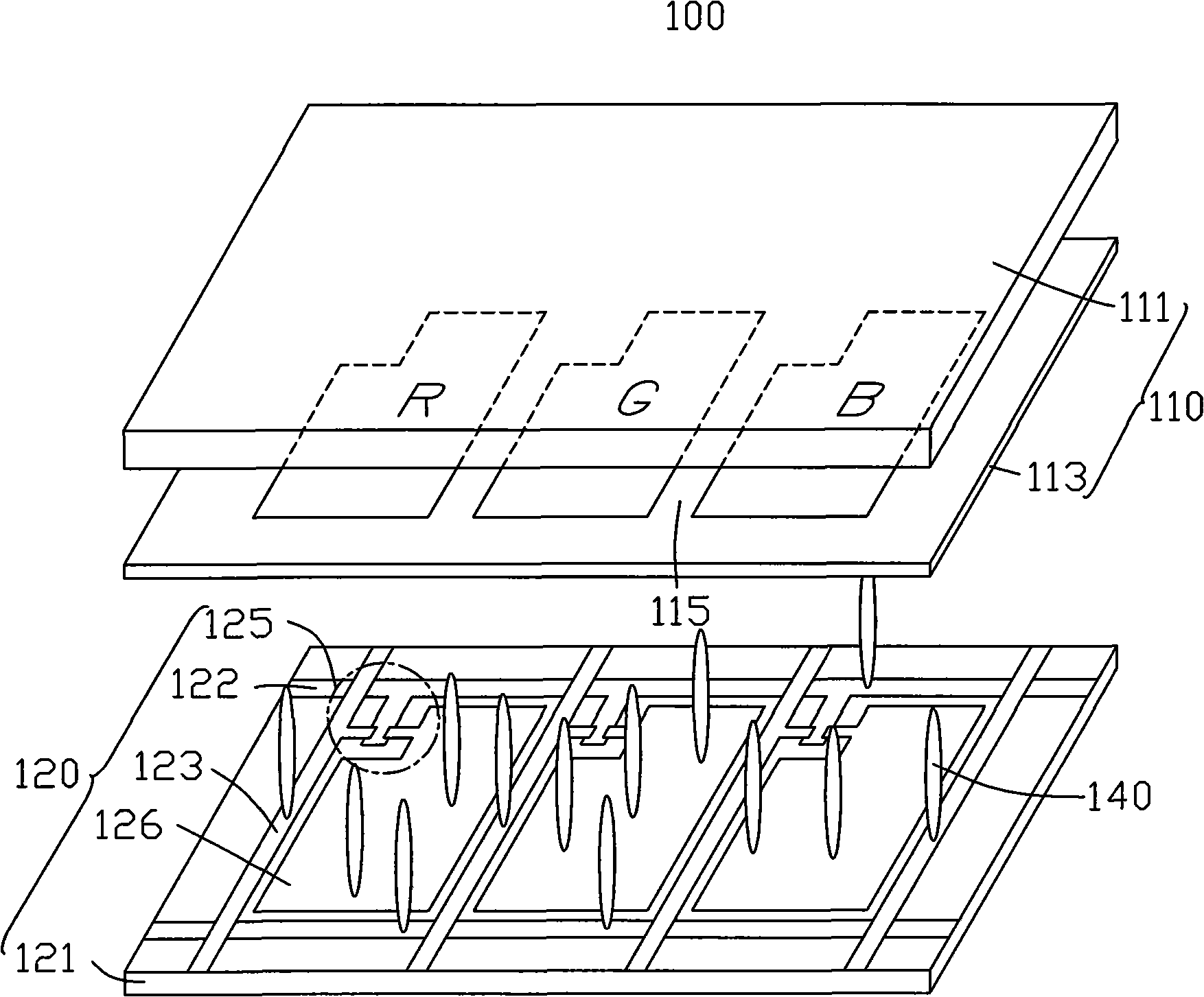
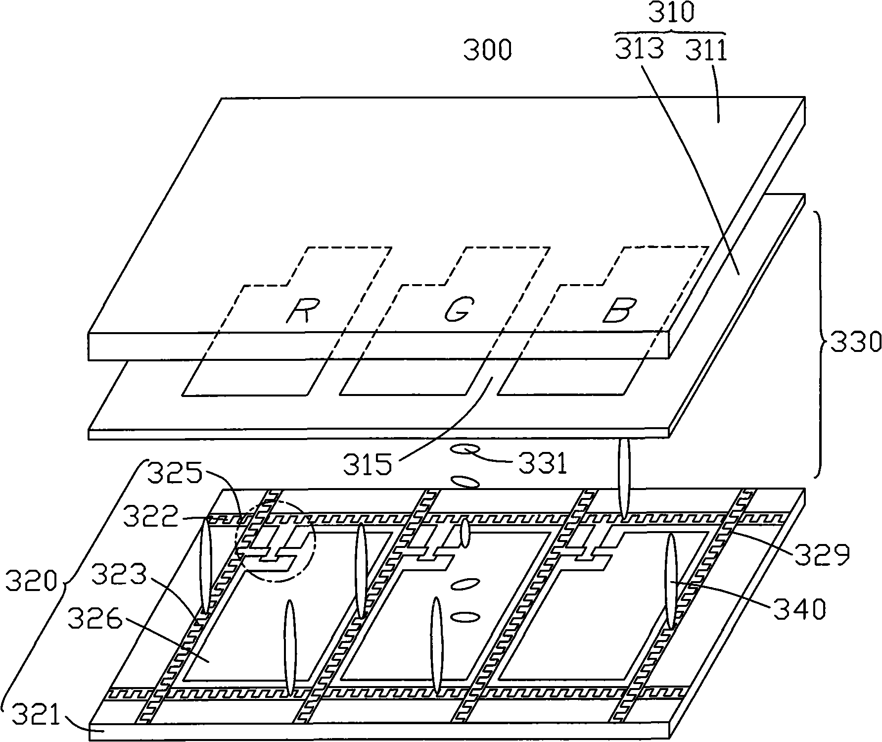
[0025] see image 3 , is a schematic cross-sectional structure diagram of the first embodiment of the liquid crystal display panel of the present invention. The liquid crystal display panel 300 includes a thin film transistor substrate 320, a color filter substrate 310 disposed opposite to the thin film transistor substrate 320, a liquid crystal layer 330 sandwiched between the two substrates 310, 320 and a plurality of A spacer 340 between the two substrates 310 , 320 . The liquid crystal layer 330 includes a plurality of liquid crystal molecules 331 .

[0026] A portion of the TFT substrate 320 adjacent to the liquid crystal layer 330 forms a plurality of concave structures 329 , and the spacers 340 are disposed in the concave structures 329 . The spacer 340 is used to separate the two substrates 310 , 320 so that the two substrates 310 , 320 maintain a consistent distance, thereby forming a cell gap to accommodate the liquid crystal molecules 331 .

[0027] The color fil...


PUM


Abstract

The invention provides a liquid crystal display panel, comprising a colourful filter sheet substrate, a film transistor substrate which is arranged correspondingly to the colourful filter sheet substrate, a liquid crystal layer which is sandwiched between the two substrates and a plurality of barriers which are sandwiched between the two substrates. One side of at least one substrate adjacent to the liquid crystal layer is provided with a plurality of concave structures and the barriers are arranged inside the concave structure.

Description

technical field [0001] The invention relates to a liquid crystal display panel. Background technique [0002] Liquid crystal display devices have the advantages of no radiation, thinness, and power saving, and have been widely used in various information, communication, and consumer products. A liquid crystal display device generally includes a liquid crystal display panel. [0003] see figure 1 , is a schematic cross-sectional structure diagram of a liquid crystal display panel in the prior art. The liquid crystal display panel 100 includes a thin film transistor substrate 120, a color filter substrate 110 disposed opposite to the thin film transistor substrate 120, a liquid crystal layer 130 sandwiched between the two substrates 110, 120, and a plurality of evenly distributed Spacers 140 in the liquid crystal layer 130 . The liquid crystal layer 130 includes a plurality of liquid crystal molecules 131 . [0004] The spacer 140 is used to separate the two substrates 11...

Claims


Application Information

Patent Timeline
Patent Type & Authority Applications(China)
IPC IPC(8): G02F1/1339G02F1/133
CPCG02F1/133512G02F1/13394
Inventor 黄信杰吴佳怡萧坤星
Owner INNOCOM TECH (SHENZHEN) CO LTD
Why Eureka
Try Eureka