Metallic face sandwiched composite board and assembled composite wall panel

A sandwich composite panel and composite wall panel technology, which is applied in the direction of building components, buildings, building structures, etc., can solve the problem that there is no suitable horizontal typesetting metal surface polystyrene sandwich composite panel, which cannot meet the requirements of novel and diverse architectural shapes. requirements, no problems such as horizontal typesetting, to achieve the effect of increasing visual beauty, not easy to confuse, and preventing slipping

Active Publication Date: 2009-01-07
HENAN TIANFON ENERGY SAVING PANEL SCI & TECH
View PDF0 Cites 11 Cited by
  • Summary
  • Abstract
  • Description
  • Claims
  • Application Information

AI Technical Summary

Problems solved by technology

[0003] At present, the composite wallboards assembled from metal-faced polyurethane sandwich composite panels have two types of layouts: horizontal and vertical. There are also many forms of joints for metal-faced polyurethane sandwich composite panels that are suitable for each type of layout. Designers can have more choices when designing houses. However, it still cannot meet the growing demand for novel and diverse architectural shapes.
The composite wallboards assembled from polystyrene sandwich composite panels with metal surfaces generally use the vertical typesetting method. There is no horizontal typesetting method, and there is no metal-faced polystyrene sandwich composite panel suitable for horizontal typesetting

Method used


Image

  • Metallic face sandwiched composite board and assembled composite wall panel
  • Metallic face sandwiched composite board and assembled composite wall panel
  • Metallic face sandwiched composite board and assembled composite wall panel

Examples


Embodiment Construction

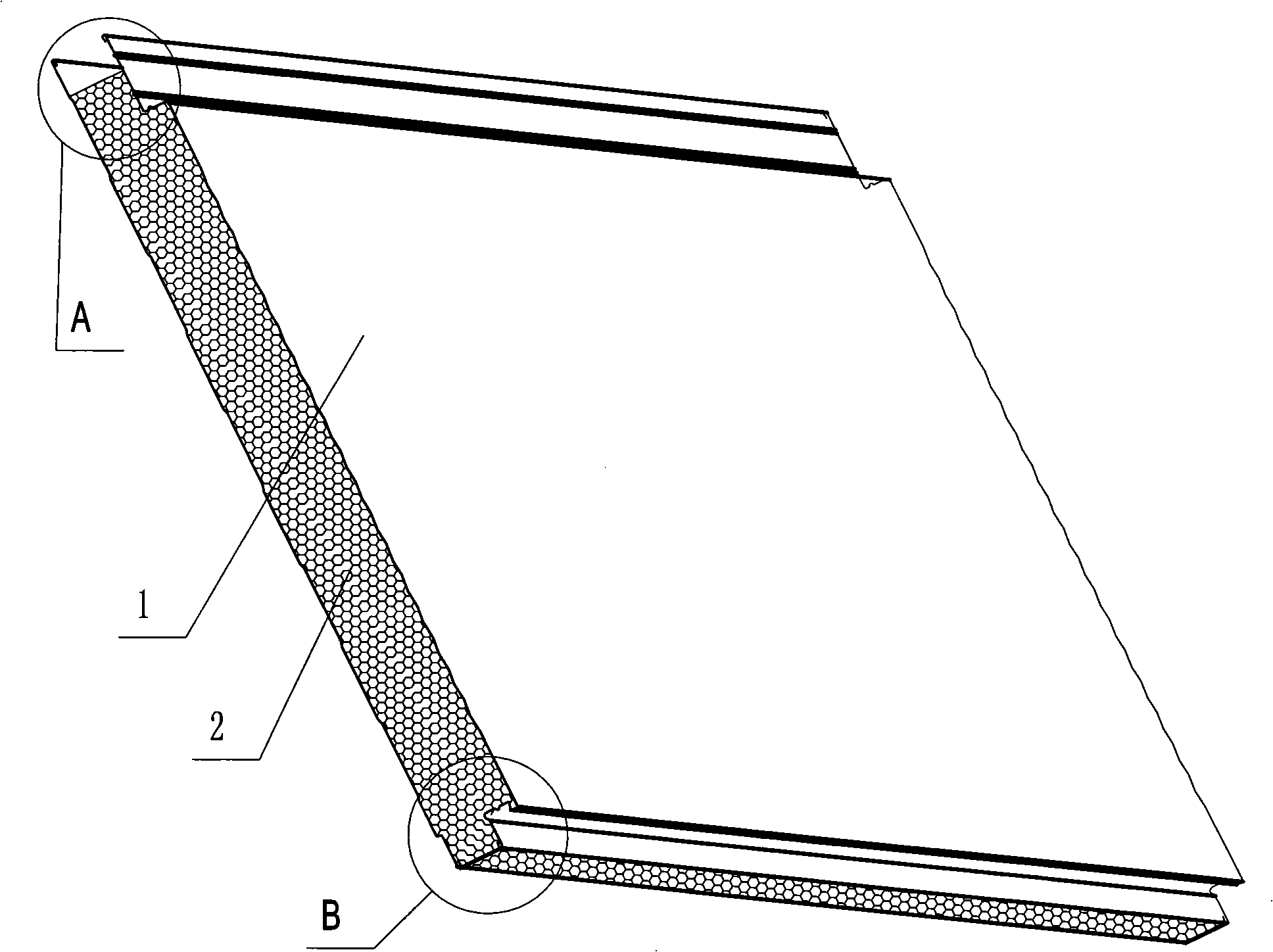
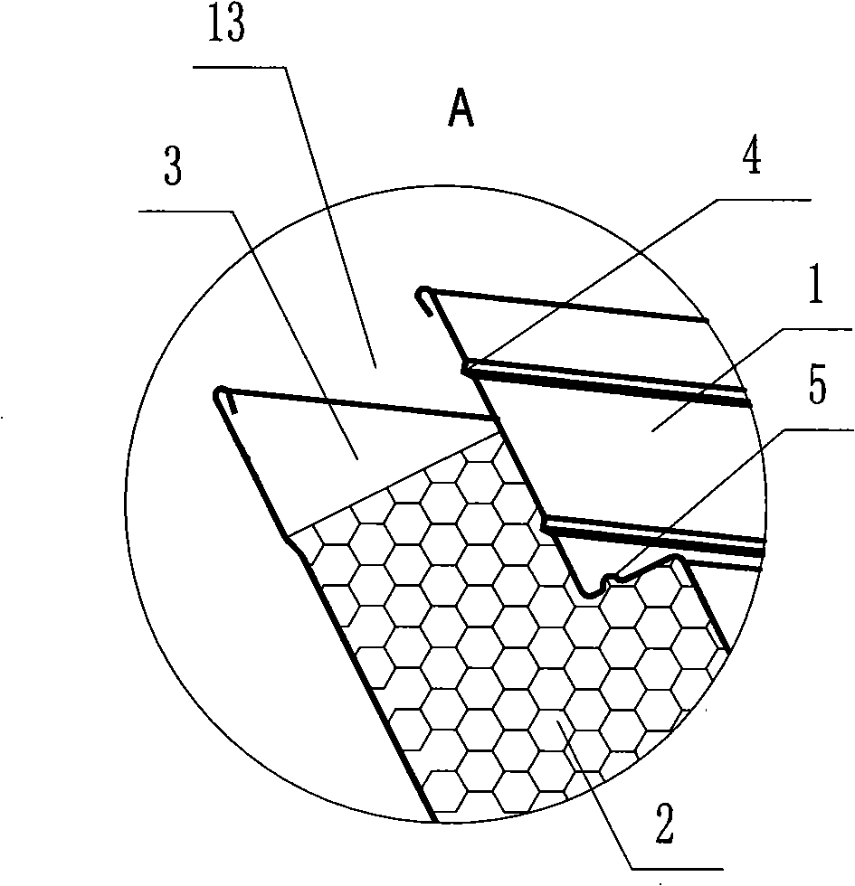
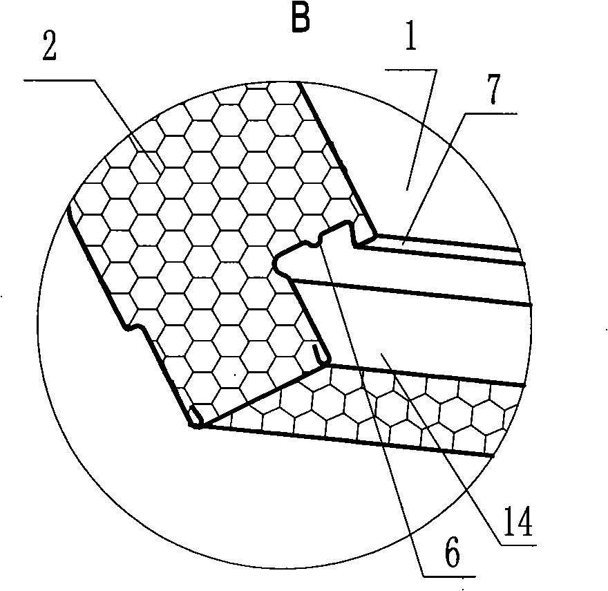
[0023] figure 1 , figure 2 , image 3 The metal-face sandwich composite panel shown includes an outer panel 1, an inner panel 3 and a sandwich layer 2 between the two panels. The two opposite splicing ends on the composite panel are the insertion slot end A and the insertion head end respectively. B. At the end of the insertion groove, the end of the outer panel 1 is bent inward to form a fixed platform with a height lower than the composite panel surface, the end wall of the outer panel 1 and the end wall of the inner panel 3 and the sandwich layer 2 The end faces of the two together form an insertion groove 13, and a nail groove 4 parallel to the edge of the composite board is provided on the board surface of the fixed platform; at the insertion head end, the end of the outer panel is bent to a height lower than that of the composite board. The top of the surface, the end of the outer panel, the end of the inner panel and the end surface of the sandwich layer together con...


PUM


Abstract

The invention relates to a metal-surface sandwich composite board and assembly composite wall board which comprises two or more pieces of metal-surface sandwich composite board arranged on a fixing frame. Each composite board is provided with two matching terminals which are opposite, wherein, one is an inserting groove terminal, and the other is an inserting head terminal. At the inserting groove terminal, the end of an external face plate is bent inward to form a fixing platform which is slightly lower than the board surface of the composite board; the wall surface of the end of the external face plate, the wall surface of the end of an internal face plate and the end surface of a sandwich layer form an inserting groove. At the inserting head terminal, the end of the external face plate is bent to from a platform which is slightly lower than the board surface of the composite board; and the wall surface of the end of the external face plate, the wall surface of the end of the internal face plate and the end surface of the sandwich layer form an inserting head which is matched with the inserting groove. Two adjacent composite boards are assembled together by jointing the inserting groove of one composite board with the inserting head of the other composite board; an installing groove is formed at the place of the joint; and in the installing groove, a decoration sealing buckle plate is arranged in a buckling way to play the sealing, decorating and thermal-insulation function.

Description

technical field [0001] The invention belongs to the technical field of building materials, in particular to a metal surface sandwich composite panel used in a steel structure enclosure system and an assembled composite wallboard composed of a metal surface sandwich composite panel. Background technique [0002] The main part of the steel structure enclosure system is assembled composite wall panels. After the completion of the steel structure frame system, the assembled composite wall panels are installed on the steel structure frame with purlins, and then the metal surface sandwich composite panels are assembled according to certain conditions. The assembly method is fixed on the purlins to form a whole wall panel. The metal sandwich composite panel is composed of two metal panels and a sandwich layer filled between the two metal panels. There are corresponding splicing joints on the two opposite splicing ends of the sandwich composite board. The splicing forms include lap...

Claims


Application Information

Patent Timeline
Patent Type & Authority Applications(China)
IPC IPC(8): E04C2/34E04C2/38E04C2/292E04B1/61
Inventor 胡文悌李晓博王颖谢柯崔东红王国柱郭呈亮余海霞张志娜郭非李少华曹亮
Owner HENAN TIANFON ENERGY SAVING PANEL SCI & TECH
Why Eureka
Try Eureka