Reciprocating-piston compressor body

A compressor and reciprocating technology, applied in the field of compressors, can solve the problems that cannot fully reflect the advantages of the crank and slider mechanism, and achieve the effects of low cost, easy transportation, and simple processing

Active Publication Date: 2009-01-07
BEIJING SINOCEP ENGINE TECH
View PDF6 Cites 7 Cited by
  • Summary
  • Abstract
  • Description
  • Claims
  • Application Information

AI Technical Summary

Problems solved by technology

However, the body provided in the above-mentioned patent cannot fully reflect the advantages of the above-mentioned crank-slider mecha

Method used


Image

  • Reciprocating-piston compressor body
  • Reciprocating-piston compressor body
  • Reciprocating-piston compressor body

Examples


Example Embodiment

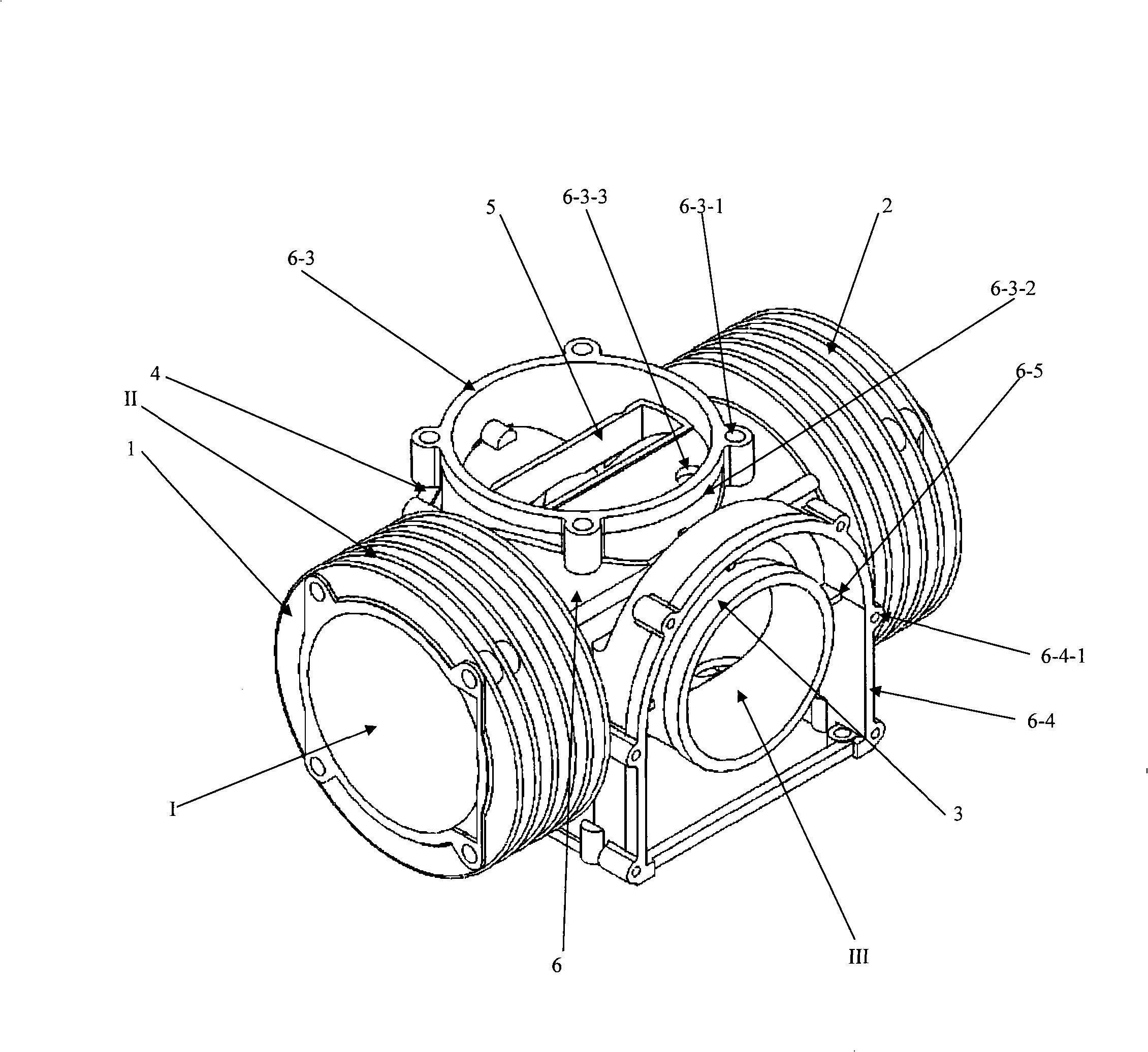
[0025] The first embodiment of the present invention provides a compressor body adopting a crank circular slider mechanism. The compressor adopts a piston with a working part at both ends and a single working part piston that functions as a starting balance slider. The compressor constitutes an inverted T-shaped three-cylinder compressor.

[0026] According to the structural principle of the above-mentioned crank circular slider mechanism, the body needs to provide movement space for the piston and the dynamic balance slider, and provide support for the crankshaft.

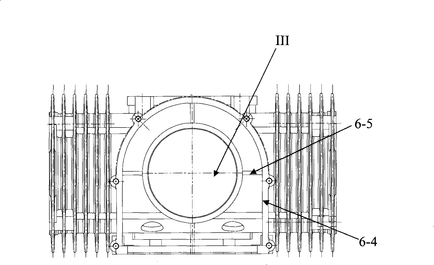
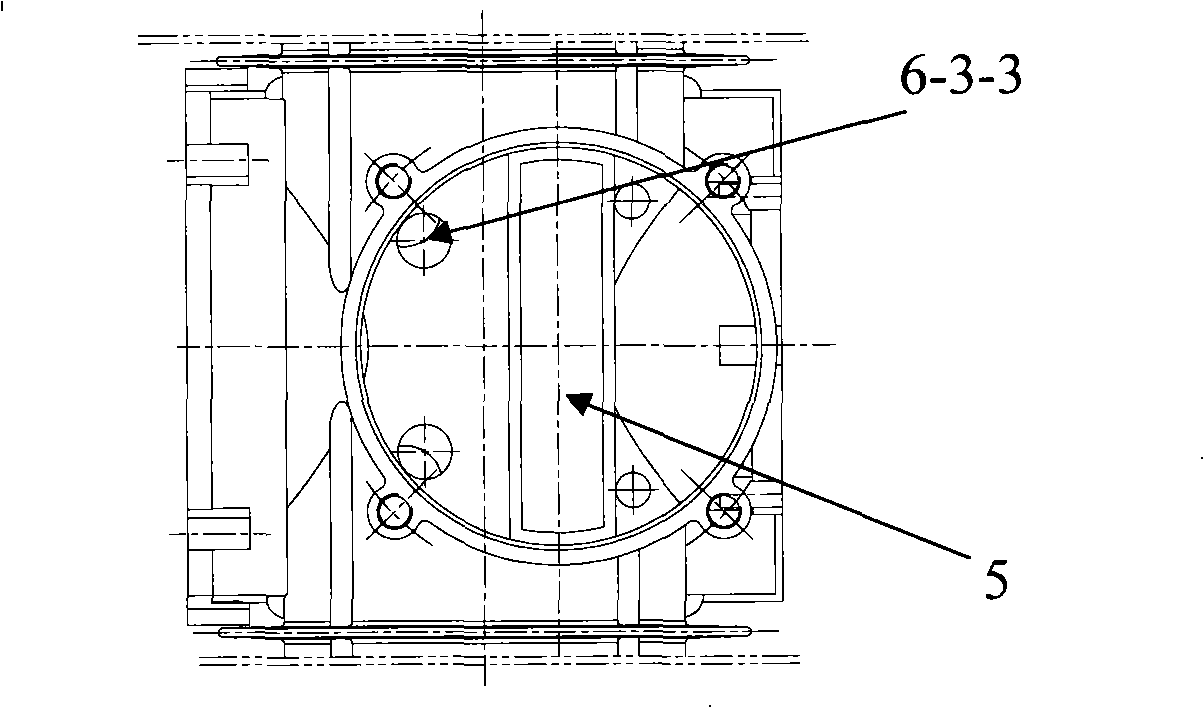
[0027] Please see figure 1 , The figure shows the axial view of the body, from which the basic structure of the body can be seen. The body includes a first cylinder liner 1, a second cylinder liner 2, a first main bearing hole 3, a second main bearing hole 4, a slideway 5, and the above-mentioned components are connected together by a base 6 with an intermediate position as a basic frame. Also, please see Figure 2-Fi...


PUM


Abstract

The present invention discloses a reciprocating compressor block, which comprises a basal body, a first main bearing hole, a second main bearing hole, one or two horizontally arranged cylinder sleeves and a slideway; wherein, the basal body is a cavity; both the first and the second main bearing holes are cylindrical sleeves; the axes of the bearing hole cavities of the cylindrical sleeves are on the same line, and the cylindrical sleeves are symmetrically arranged on the front and the rear sides of the basal body and communicated with each other through a throughhole on the basal body. When two cylinder sleeves are adopted, the two cylinder sleeves are cylindrical sleeves, the axes of the cylinder sleeve cavities of the cylindrical sleeves are on the same line, the cylindrical sleeves are arranged on the left and the right sides of the basal body, and the axes of the bearing hole cavities are vertically intersected with the axes of the cylinder sleeve cavities on the same plane. The slideway is a flat and long throughhole which is positioned on the top of the basal body, the central plane of the slideway on a width direction is parallel to the axes of the cylinder sleeve cavities and is spaced from the axes of the cylinder sleeve cavities for a preset distance on the vertical direction. The reciprocating compressor block is applicable to a compressor adopting a crank-slider mechanism.

Description

technical field [0001] The invention relates to compressor technology, in particular to a reciprocating compressor body. Background technique [0002] Generally, the so-called compressor refers to the compressor used in the refrigeration system. This compressor uses the mechanical energy provided by the prime mover to suck in low-temperature and low-pressure refrigerant gas from the suction pipe, compress it, and discharge it to the exhaust pipe. The high-temperature and high-pressure refrigerant gas provides power for the refrigeration cycle, thereby realizing the refrigeration cycle of compression→condensation→expansion→evaporation and heat absorption. In addition, air compressors referred to as air compressors are often used in production practice. This air compressor also uses the machinery of the prime mover to convert ordinary-pressure air into high-pressure gas as a source of compressed air. The above-mentioned compressors and air compressors belong to the broad conc...

Claims


Application Information

Patent Timeline
IPC IPC(8): F04B39/12F04B39/00
Inventor 黎明黎正中
Owner BEIJING SINOCEP ENGINE TECH
Why Eureka
Try Eureka