Improvements in or relating to current differential protection relays

A protection relay and differential protection technology, applied in multiple unbalanced current/voltage switches, emergency protection circuit devices, emergency protection devices with automatic disconnection, etc. Relay reliability, reducing the sensitivity of protection relays, etc.

Inactive Publication Date: 2009-01-07
AREVA T& D UK
View PDF2 Cites 7 Cited by
  • Summary
  • Abstract
  • Description
  • Claims
  • Application Information

AI Technical Summary

Problems solved by technology

[0006] However, a disadvantage of this method is that reducing the sensitivity of the protective relay also reduces the ability of the protective relay to detect faults that require isolation of the protected area, thereby reducing the reliability of the protective relay

Method used


Image

  • Improvements in or relating to current differential protection relays
  • Improvements in or relating to current differential protection relays
  • Improvements in or relating to current differential protection relays

Examples


Embodiment Construction

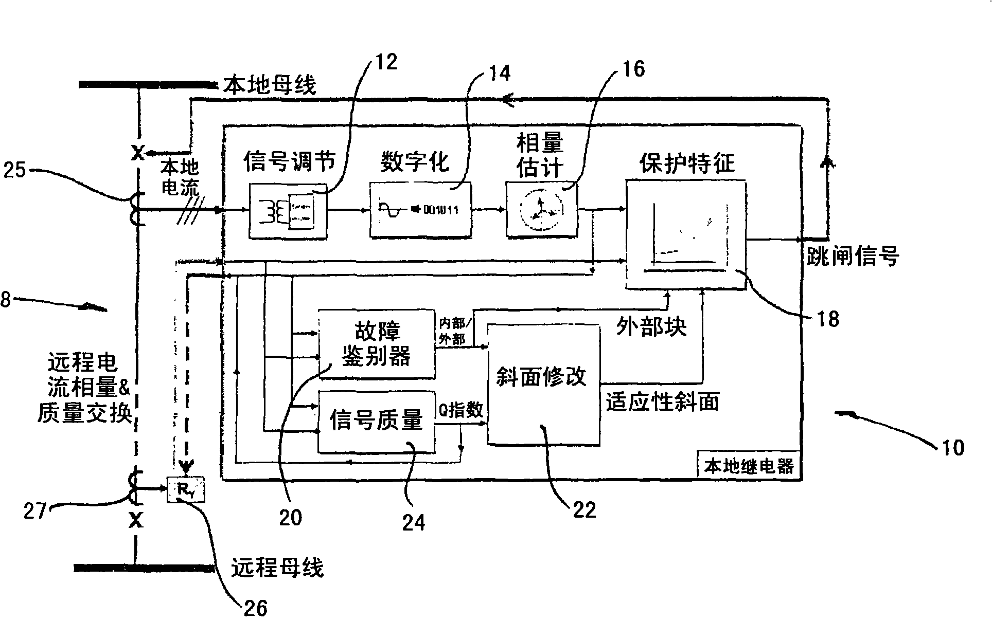
[0026] figure 1 A schematic diagram of a protected area 8 in a three-phase power system is shown.

[0027] The protected area 8 is defined by two sets of current transformers as follows: a first set of three local current transformers each corresponding to a phase at one end of the protected area 8 (at figure 1 Only one local current transformer 25 is shown in ; and a second set of three remote current transformers each corresponding to a phase at the other end of the protected area 8 ( figure 1 Only one local current transformer 27 is shown in .

[0028] Each local current transformer 25 is electrically coupled to a protective relay (in figure 1 Only one protective relay 10 is schematically shown in , and each remote current transformer 27 is electrically coupled to the other protective relays (in figure 1 Only one other protective relay 26 is shown in . Protective relay 10,26 has and figure 1 The same configuration as shown in the protective relay 10.

[0029] In pract...


PUM


Abstract

In the field of current differential protection relays there is a need for improvements in or relating to the protection relays to allow them to accommodate current transformer saturation while maintaining a desired degree of reliability. A method of operating a current differential protection relay (10, 26) following a fault, the protection relay (10, 26) being electrically coupled to a protection zone of an electrical power system, comprises the steps of establishing a fault condition by discriminating between an internal fault inside the protection zone and an external fault outside the protection zone; and modifying the sensitivity of the protection relay (10, 26) according to the nature of the fault condition. A current differential protection relay (10, 26) comprises a fault discriminator module (20) to establish a fault condition by discriminating between an internal fault inside a protection zone of an electrical power system and an external fault outside the protection zone; and a sensitivity modifying module (22) to modify the sensitivity of the protection relay according to the nature of the fault condition.

Description

technical field [0001] The invention relates in particular, but not exclusively, to a method of operating a current differential protective relay electrically coupled to a protected area of ​​a power system, a method of protecting a protected area of ​​a different power system coupled with a current differential protective relay, and A current differential protection relay. Background technique [0002] A protected area may include a transmission line with two ends, or, for example, one or more transformers, busbars, or motors. [0003] The electrical components described above are important components of power transmission systems and may be protected using line current differential protection relays, each electrically coupled to the electrical components via current transformers. As soon as a fault is detected, a given protective relay trips in order to isolate said electrical components within the protected area. [0004] Errors produced by current transformers and satu...

Claims


Application Information

Patent Timeline
Patent Type & Authority Applications(China)
IPC IPC(8): H02H3/28H01H83/14
CPCH02H3/006H02H3/286
Inventor P·K·甘加德哈兰T·S·希胡
Owner AREVA T& D UK
Why Eureka
Try Eureka