
Flat dispersion frequency discriminator (FDFD)

a frequency discriminator and flat-band technology, applied in the field of frequency discrimination, can solve the problems of optical signal distortion and limit the minimum bandwidth of filters in this application, and achieve the effect of minimizing the occurrence of distortion

Inactive Publication Date: 2006-05-30
II VI DELAWARE INC
View PDF10 Cites 98 Cited by
  • Summary
  • Abstract
  • Description
  • Claims
  • Application Information

AI Technical Summary

Benefits of technology

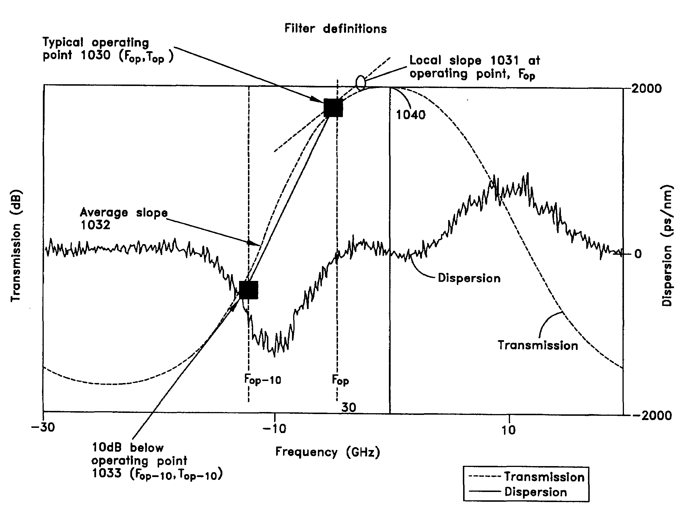
The invention provides a flat dispersion frequency discriminator (FDFD) that can have a flat dispersion in either positive or negative dispersion along the spectrum region of the discriminator. This means that the FDFD does not cause distortion of the intensity pattern of its output, minimizing the occurrence of distortion due to overshooting or undershooting of the intensity pattern depending on the relative spectral alignment of the laser output relative to the filter transmission. This is achieved by providing a filter that has a spectral profile described by a quadratic coefficient of logarithmic transmission with optical frequency and a substantially negative dispersion on the high frequency side of the transmission peak and a substantially positive dispersion on the high frequency side of the transmission peak. The filter can be designed for a particular fiber optic application by determining an ideal dispersion curve for it. The patent text also mentions that there are many modifications, variations, and combinations of the methods and systems and apparatus of a dispersion compensated optical filter that can be made based on the embodiments described herein.

Problems solved by technology

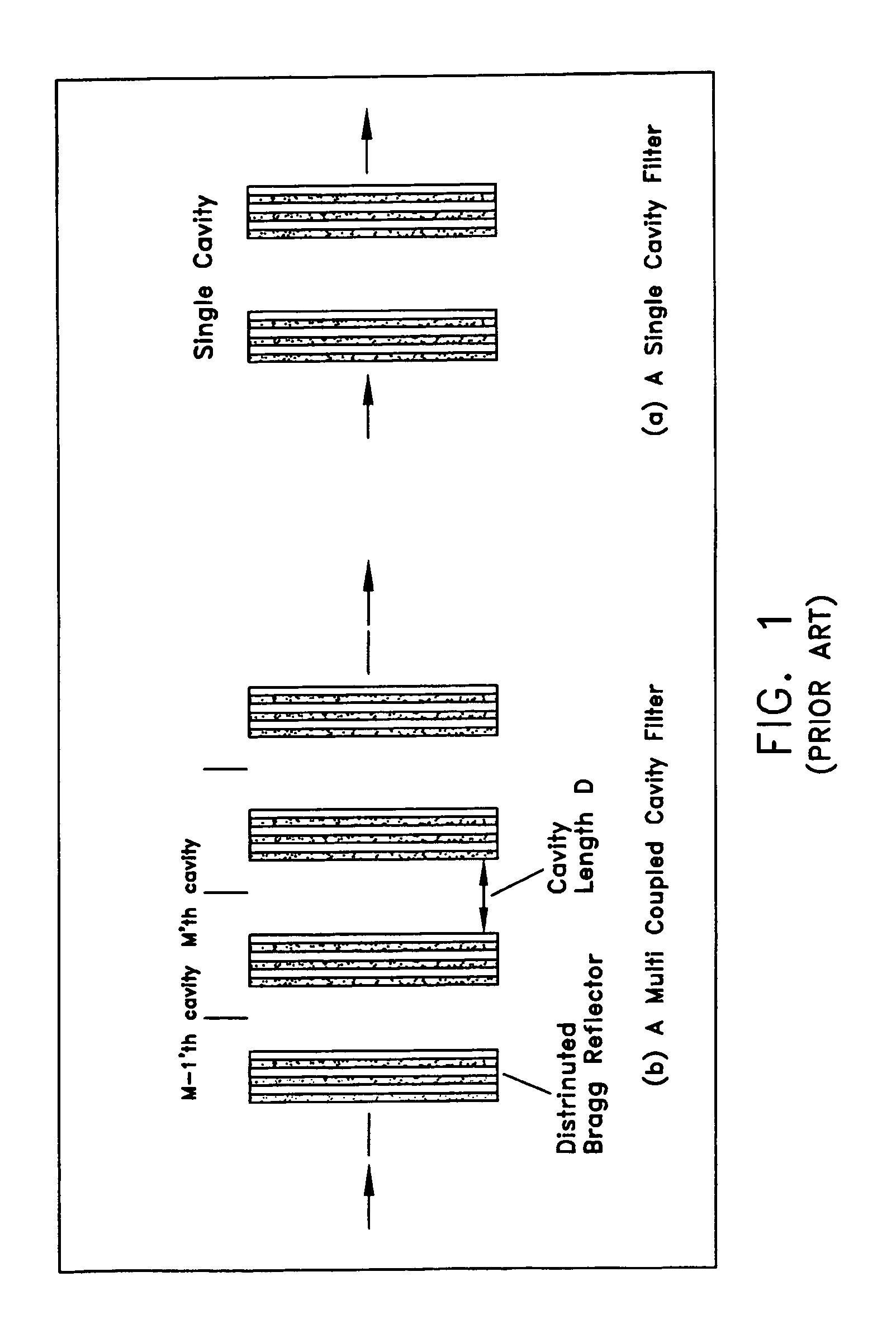
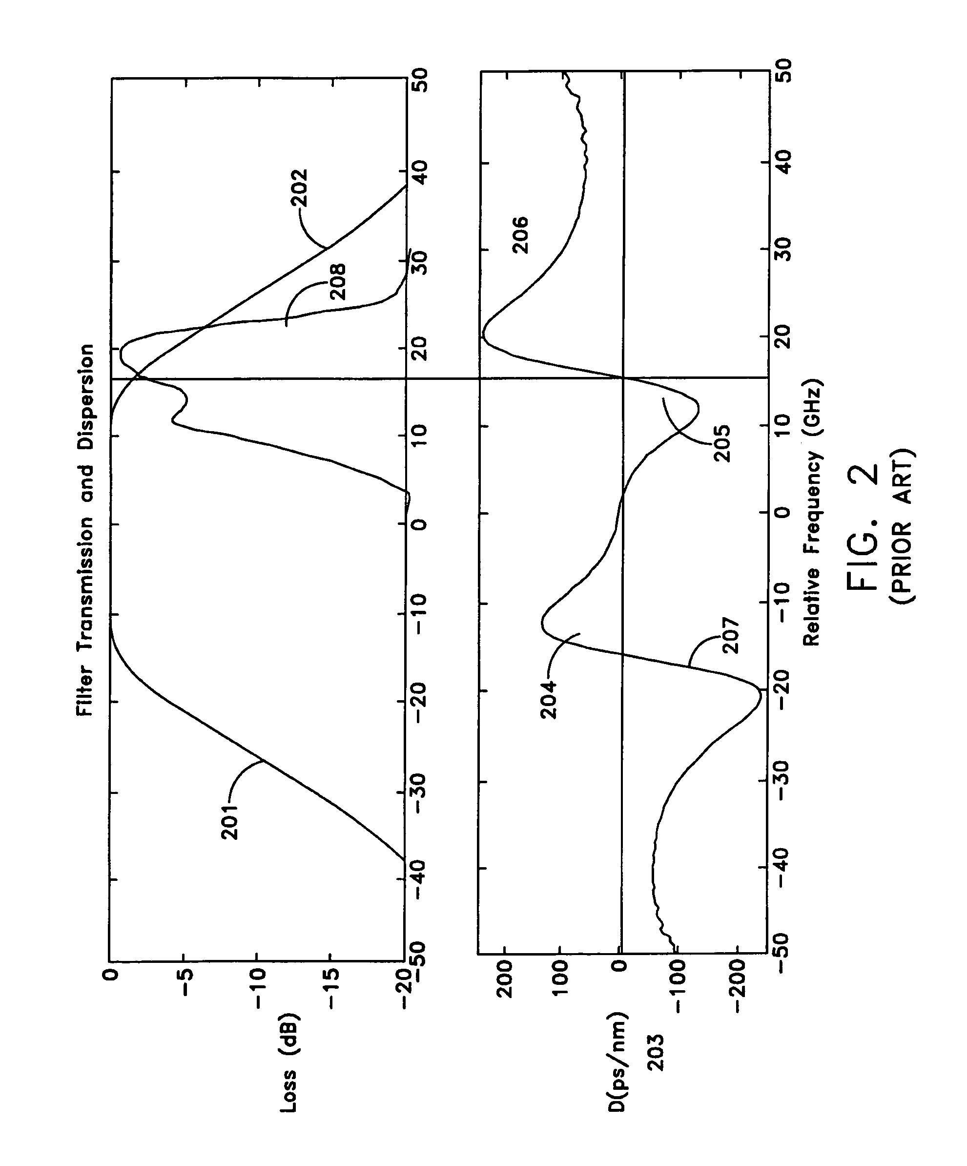
Besides the alignment, the three-cavity design may have rapid variation of dispersion with optical frequency that causes distortions of the optical signal due to third order dispersion.
However, the positive slope discriminator has a positive dispersion for the typical filter illustrated in FIG. 3 where it can only compensate for negative dispersion fiber.
This provides a limitation on the minimum bandwidth that a filter can have in this application.

Method used


Image

  • Flat dispersion frequency discriminator (FDFD)
  • Flat dispersion frequency discriminator (FDFD)
  • Flat dispersion frequency discriminator (FDFD)

Examples


Embodiment Construction

[0044]The transmission spectrum of the FDFD filter may be determined based on the following. An ideal dispersion curve for a particular filter application is defined. Based on the ideal dispersion curve, the corresponding phase may be obtained. Then, the Kramers-Kronig relationship may be applied to calculate the transmission spectrum. A standard optimization and filter design package may be then used to synthesize the desired filter function starting from a close approximation. For example, a FDFD based on a 93 layer CMC may be used.

[0045]FIG. 6(a) illustrates that the filter dispersion may be selected so that it is equal to a negative constant −Dm for a finite band of frequencies, 2ω0, on the low frequency side of a center frequency, and equal to +Dm for a finite band of frequencies 2ω0 on the high frequency side of the center frequency. The frequency relative to the center frequency may be defined where the dispersion is defined in units of ps / nm and is related to the phase of th...


PUM


Abstract

This invention provides a flat dispersion frequency discriminator (FDFD) capable of having a substantially flat dispersion with either a positive or negative dispersion along the spectrum region of the discriminator. This way, a FDFD may not cause substantial distortion of the intensity patter of its output to minimize the occurrence distortion due to overshooting or undershooting of the intensity pattern depending on the relative spectral alignment of the laser output relative to the filter transmission.

Description

RELATED APPLICATION[0001]This application claims priority to U.S. Provisional Application No. 60 / 416,102, filed Oct. 4, 2002, which is hereby incorporated by reference. In addition, U.S. patent application Ser. No. 10 / 289,944, entitled Power Source for a Dispersion Compensation Fiber Optic System filed Nov. 6, 2002, is hereby incorporated by reference.BACKGROUND OF THE INVENTION[0002]1. Field of the Invention[0003]This invention provides a frequency discrimination capable of providing a substantially flat dispersion in a fiber optic system.[0004]2. General Background[0005]A frequency modulated laser source is modulated with digital data and the resulting output is passed through an optical frequency discriminator. The input to the discriminator is arranged to have a small amplitude modulation and sufficiently large frequency modulation. The frequency discriminator (FD) increases the extinction ratio of the output. In a fiber optic transmission system, which is limited by fiber dispe...

Claims


Application Information

Patent Timeline
Patent Type & Authority Patents(United States)
IPC IPC(8): G02B6/00G02B6/26G02B6/42G02B6/34H04B10/18
CPCG02B5/288G02B6/29358H04B10/25133G02B6/29394G02B6/29392
Inventor MAHGEREFTEH, DANIELWALKER, DUNCAN JOHN WILLIAMNUYTS, ROELAND
Owner II VI DELAWARE INC
Learn More