
Resonant tracking non-contact power supply device and power supply method

A non-contact power supply and tracking technology, which is applied in the direction of circuit devices, electrical components, electromagnetic wave systems, etc., can solve the problems of large-scale changes in the receiving end voltage, low coupling coefficient of the coupling channel, increasing the difficulty and cost of the design of the power supply circuit of the subsequent stage, etc. , to achieve the effect of reducing design difficulty and cost

Inactive Publication Date: 2010-09-15
XIDIAN UNIV
View PDF3 Cites 90 Cited by
  • Summary
  • Abstract
  • Description
  • Claims
  • Application Information

AI Technical Summary

Problems solved by technology

Therefore, the distance between the transmitting and receiving coils needs to be relatively fixed, which limits the scope of application
[0007] Secondly, due to the low coupling coefficient of the coupling channel, when the load at the receiving end changes in a large range, the voltage at the receiving end will vary in a large range
The load at the receiving end is required to be relatively constant, and at the same time, it increases the design difficulty and cost of the power supply circuit of the subsequent stage

Method used


Image

  • Resonant tracking non-contact power supply device and power supply method
  • Resonant tracking non-contact power supply device and power supply method
  • Resonant tracking non-contact power supply device and power supply method

Examples


Embodiment Construction

[0033] The present invention will be further described below in conjunction with embodiment.

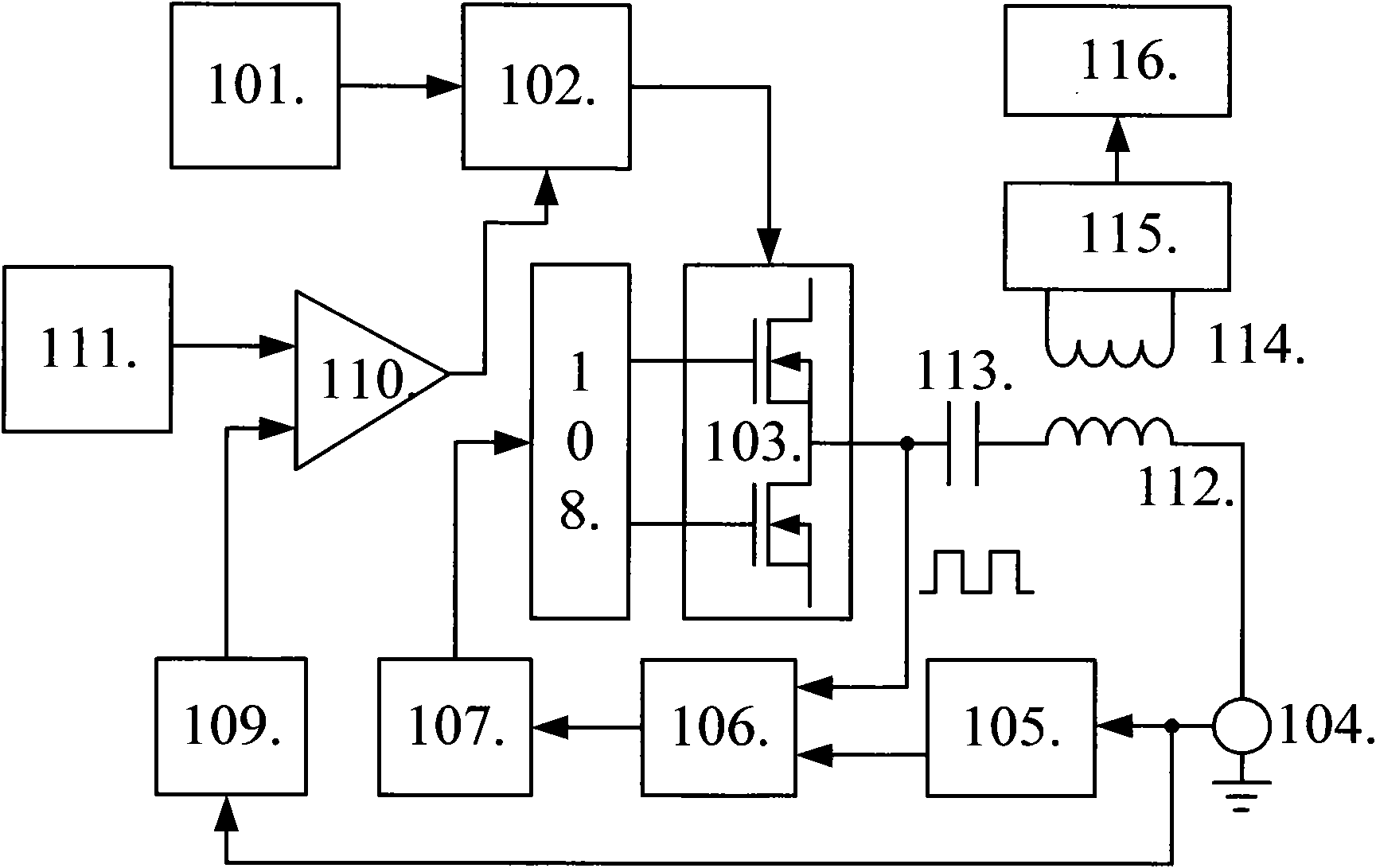
[0034] refer to figure 1Embodiment 1 of the present invention consists of a DC power supply 101, a switching power supply circuit 102, a MOS tube half-bridge switch 103, a current sampler 104, a zero-crossing comparator 105, a phase detector 106, a voltage-controlled oscillator 107, a floating gate driver 108, Detecting and filtering circuit 109 , error amplifier 110 , reference voltage 111 , power transmitting coil 112 , resonant capacitor 113 , power receiving coil 114 , rectifying and stabilizing circuit 115 , and load 116 . Among them, the switching power supply 102 adopts a synchronous step-down mode, and the amplitude is adjustable from 0 to 100%. Its input terminal is from the DC power supply 101, and its output is connected to the MOS tube half-bridge switch 103 to form a high-power excitation source; the MOS tube half-bridge switch 103 The output passes through the resonant...


PUM


Abstract

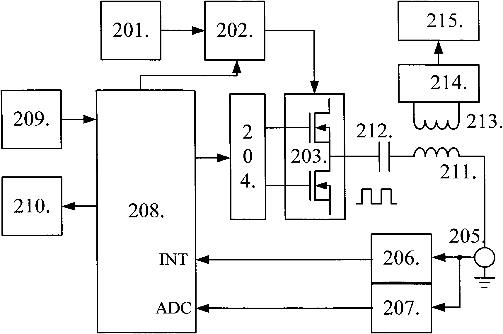
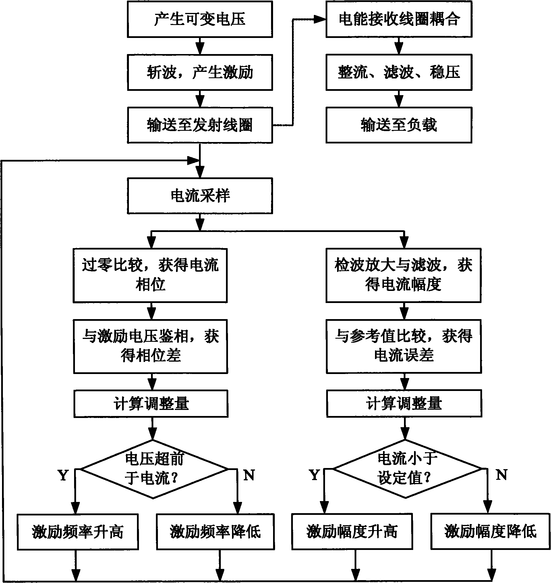
The invention discloses a resonant tracking non-contact power supply device and a resonant tracking non-contact power supply method and aims to mainly solve the problems that the transmission efficiency and transmission distance are reduced and induction voltage is sensitive to load change caused by the change of a resonant point in an LC resonant non-contact power supply. An excitation source with adjustable frequency and amplitude is formed through an adjustable switch power source (102) and a half-bridge switch (103) and is applied to a resonant circuit consisting of an emitting coil (112) and a resonant capacitor (113); a current signal in the resonant circuit is acquired by using a current sampler (104); an automatic resonant frequency tracking circuit consists of a comparator (105), a phase discriminator (106) and a controllable oscillator (107); when the resonant point changes, an excitation frequency is automatically adjusted and an automatic excitation voltage adjusting circuit consists of a wave detecting and filtering circuit (109), an error amplifier (110) and the adjustable switch power source (102) to automatically adjust the excitation voltage when a load changes, so a load voltage is basically constant. The resonant tracking non-contact power supply device can overcome the effects caused by resonant frequency change and load change and is applicable for the occasion of close-range and high-efficiency non-contact power transmission.

Description

technical field [0001] The invention belongs to the technical field of power supply / power electronics and relates to a non-contact power supply method, which can be used to supply power to rotating parts, machine joints, waterproof equipment, kitchen and bath appliances, mobile / portable equipment and underground equipment. Background technique [0002] As a new form of energy transmission, non-contact power supply has the characteristics of no contact, no wear, no spark, fully sealed, waterproof and explosion-proof, and is gradually being applied to rotating parts, machine joints, waterproof equipment, kitchen / Bathroom appliances, mobile / portable equipment and underground equipment and other fields. [0003] The existing non-contact power supply generally uses a magnetic material and a coil to form a loosely coupled transformer as an energy transmission channel. The excitation voltage is applied to the primary coil to excite an alternating magnetic field in space, and the m...

Claims


Application Information

Patent Timeline
IPC IPC(8): H02J17/00H02J50/12
Inventor 谢楷李小平刘彦明郭世忠刘东林屈辰
Owner XIDIAN UNIV
Learn More