Apparatus for collecting bee poison

A kind of equipment, bee venom technology, applied in the direction of honey collection, beehive, application, etc., can solve the problems of short circuit, bee killing, wire entanglement, etc., and achieve the effect of convenient use and safe weight

Inactive Publication Date: 2011-04-20
REPUBLIC OF KOREA (MANAGEMENT RURAL DEV ADMINISTRATION) +1
View PDF0 Cites 1 Cited by
  • Summary
  • Abstract
  • Description
  • Claims
  • Application Information

AI Technical Summary

Problems solved by technology

Currently used bee venom collector equipment is very expensive and has the problem of killing a large number of bees during the bee venom collection process
Moreover, traditional bee venom collector equipment causes serious damage to the ecological environment of bees after collecting bee venom, resulting in a reduction in honey production
[0005] In addition, most conventional bee venom collector devices do not have a structure to keep the wires tight, and thus the wires, which are usually deformed during the collection of bee venom, are easily contaminated, causing safety issues in their repeated use
Also, thus dangling wires can become entangled, exit from the glass pane, short each other, and / or increase electrical resistance due to contamination
[0006] Moreover, because conventional bee venom collector devices are generally not compatible with beehives in terms of size, auxiliary tools are required for installation, and thus conventional bee venom collector devices are inconvenient in use
[0007] Although bee venom is a product that guarantees farmers a high income, it cannot be actively collected for the above reasons
Furthermore, traditional bee venom collector equipment is too expensive to be economically attractive to the usual farm

Method used


Image

  • Apparatus for collecting bee poison
  • Apparatus for collecting bee poison
  • Apparatus for collecting bee poison

Examples


Embodiment Construction

[0029] Reference numerals shall be indicated in the drawings, wherein the use of the same reference numerals in different figures refers to the same or similar parts.

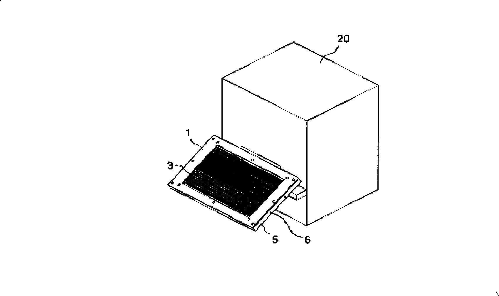
[0030] figure 1 An exploded perspective view of a bee venom collector device is shown. Such as figure 1 As shown, the bee venom collector includes a cover element 1, a pair of electric wires 3, a control rod 2 for adjusting the tension of the electric wires 3, a frame 5, a fastening element 6, a glass plate 7, a base plate 8 and a fixing element 9, on the frame 5 One side of the position forms a wire guiding device 5' for guiding the wire 3. figure 2 A plan view of a bee venom collector device of the present invention (not covered with a cover element) is shown.

[0031] image 3 shows the overall structure of the bee venom collector device of the present invention, and Figure 4 The rear of the bee venom collector of the present invention is shown in a perspective view.

[0032] As shown, in the central...


PUM


Abstract

Disclosed herein is a bee venom collector device, comprising: a covering member (1); a frame (5) to which the covering member is attached, having wire guiding grooves 5 arranged at regular intervals in one side thereof; a control bar (2), having a plurality of wire grooves (2') formed at regular intervals thereon, combined with the frame (5) at a position opposite to the guiding grooves (5') in such a way that it is movable to modulate the tension of wires guided by the wire grooves; a pair of wires (3), each being connected to both a cathode and an anode supported and guided by the guiding grooves (2') and (5') formed respectively at the control bar (2) and the frame (5), repeatedly running therebetween on tracks arranged at regular intervals according to the grooves; a glass plate, fitted in the frame (5), for receiving the bee venom; ; a base plate (8) attached at the back of the glass plate (7) to protect the glass plate; a fixing member (9) for firmly fixing the glass plate (7) and the base plate (8) in an inner space (4) of the frame; a controller (11), electrically connected to the pair of the wires (3) supported by the frame (5), for freely controlling the supply time of currents and elevating an output voltage to a predetermined level; and a power supply (15) for supplying electrical power to the controller (11).

Description

technical field [0001] The present invention relates generally to a bee venom collector device, and in particular to a bee venom collector device capable of efficiently collecting bee venom without causing physiological or ecological damage to bees, which can be easily The ground is installed and shipped and is able to hold the wires taut to prevent the wires from backing out of the glass pane, creating a short circuit or increasing resistance due to contamination. Background technique [0002] Bee venom is a poisonous substance secreted by bees, which is mainly used for defense and communication in acupuncture. Historically, bee venom has long had a good reputation for treating many diseases. There are records describing how Hippocrates used bee stings in his medical consultations some 400 years ago. The Koran, a canon of Islam, describes the treatment of bee stings for specific diseases. In Korea, bee stings have long been used in folk remedies. However, the traditiona...

Claims


Application Information

Patent Timeline
Patent Type & Authority Patents(China)
IPC IPC(8): A01K59/00
CPCA01K47/06A01K59/00
Inventor 韩相美李光吉吕奏洪权海龙禹顺玉李明烈李万泳金哲究
Owner REPUBLIC OF KOREA (MANAGEMENT RURAL DEV ADMINISTRATION)
Why Eureka
Try Eureka