
Light and color controllable illumination device and method using automatic white balance for regulation and control

An automatic white balance and lighting device technology, which is applied to lighting devices, lighting device components, lighting and heating equipment, etc., can solve the problems of lack of red light components, semiconductor lighting technology bottlenecks, semiconductor light source color rendering cannot be achieved, etc. , to achieve the effect of improving its consistency and color rendering

Inactive Publication Date: 2009-01-14
王子能
View PDF0 Cites 4 Cited by
  • Summary
  • Abstract
  • Description
  • Claims
  • Application Information

AI Technical Summary

Problems solved by technology

[0002] Daily lighting sources require good brightness, especially the consistency of chromaticity and color rendering rate. In the current semiconductor lighting technology, the generation of white light is based on the approximate white light generated by exciting yellow phosphor powder from blue light-emitting chips, but Usually, there is a lack of red light components in the white LED light source module, so that the color rendering of the semiconductor light source cannot reach above 0.9. The speed is not synchronized with the attenuation speed of other phosphors, so that the color rendering and consistency of semiconductor lighting cannot be greatly improved, and the lighting source cannot achieve the ideal lighting effect, resulting in technical bottlenecks in large-scale practical applications of semiconductor lighting

Method used


Image

  • Light and color controllable illumination device and method using automatic white balance for regulation and control
  • Light and color controllable illumination device and method using automatic white balance for regulation and control
  • Light and color controllable illumination device and method using automatic white balance for regulation and control

Examples


Embodiment Construction

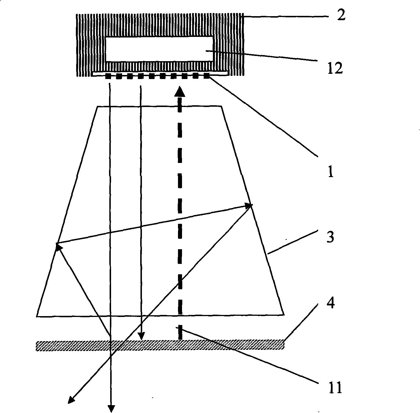
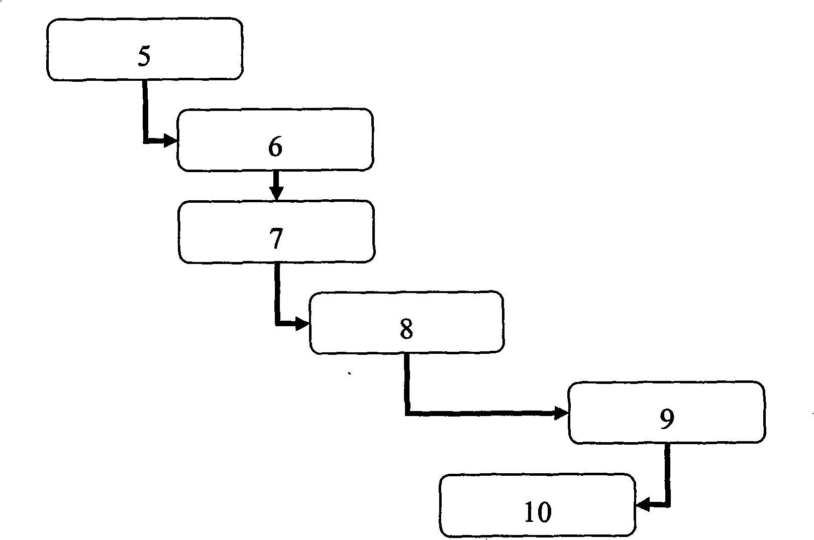
[0017] refer to figure 1 and figure 2 As shown, the lighting device of the present invention has an LED light source 1, a radiator 2, a reflector 3, a diffuser 4, a photoelectric sensor 5, a power supply circuit and a control circuit 12. Among the above, the LED light source 1 can be composed of LED components. Module structure or integrate red and white LED packages on the packaging device through semiconductor packaging technology. The photoelectric sensor 5 is installed in the LED light source 1 directly above the diffuser 4. The control circuit 12 can be made of electronic components. The control module is composed of , or integrate it on an integrated circuit through semiconductor integration technology, wherein the photoelectric sensor 5 is connected to the adaptation circuit 6, the digital-to-analog conversion circuit 7 is connected to the adaptation circuit 6, the value comparison circuit 8 is connected to the digital-to-analog conversion circuit 7, and the data proce...


PUM


Abstract

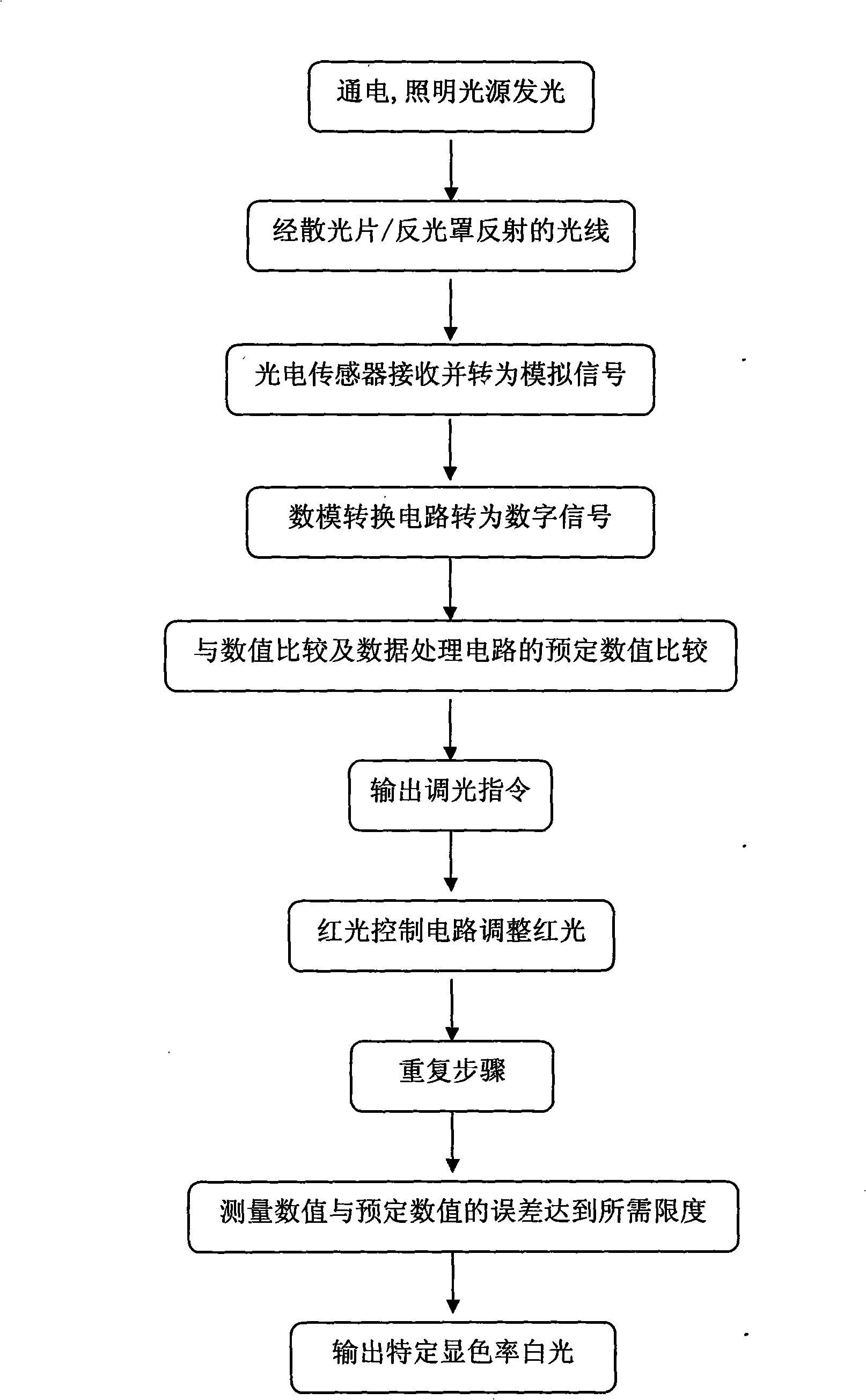
The invention provides a photochromic controllable illumination device by using automatic white balance for regulation and control, and an illumination method thereof. The illumination device comprises an LED lamp-house module, a radiator and a reflecting shade. The illumination method comprises the following steps: after the light source is connected with electricity, light rays which are shined on an astigmatic sheet by LED light source and reflected back from the reflecting shade, are received and transformed to an analog signal by a photoelectric sensor which is arranged in the LED light source, then adaptation and digital-to-analogue conversion ( A / D conversion) by an A / D conversion circuit are carried out, the comparison with a targeted value in a value comparison circuit and a data processing circuit is carried out and a light regulating instruction is output, finally, the red light output response curve of the light source is regulated by a red light control circuit, and the processes are repeated till the error between the measured value and the targeted value is within the allowed range.

Description

technical field [0001] The invention relates to an optical electronic device, in particular to an illuminating device with controllable color temperature and color rendering rate, and also relates to an illumination processing method of the illuminating device. Background technique [0002] Daily lighting sources require good brightness, especially the consistency of chromaticity and color rendering rate. In the current semiconductor lighting technology, the generation of white light is based on the approximate white light generated by exciting yellow phosphor powder from blue light-emitting chips, but Usually, there is a lack of red light components in the white LED light source module, so that the color rendering of the semiconductor light source cannot reach above 0.9. The speed is not synchronized with the attenuation speed of other phosphors, so that the color rendering and consistency of semiconductor lighting cannot be greatly improved, and the lighting source cannot ...

Claims


Application Information

Patent Timeline
IPC IPC(8): F21V23/00H05B37/02F21V13/02F21Y101/02F21Y115/10
CPCY02B20/42Y02B20/40
Inventor 王子能
Owner 王子能
Learn More