
Radio communication equipment

A technology of radio frequency communication and power amplifier module, which is applied in the direction of radio transmission system, electrical components, transmission system, etc. It can solve the problems of messy overall layout, reduce the compactness and aesthetics of the overall layout of the device, increase the difficulty of power amplifier debugging, etc., to avoid signal Loss, avoid coiling direction, reduce the effect of loss

Inactive Publication Date: 2009-01-14
COMBA TELECOM SYST CHINA LTD
View PDF0 Cites 5 Cited by
  • Summary
  • Abstract
  • Description
  • Claims
  • Application Information

AI Technical Summary

Problems solved by technology

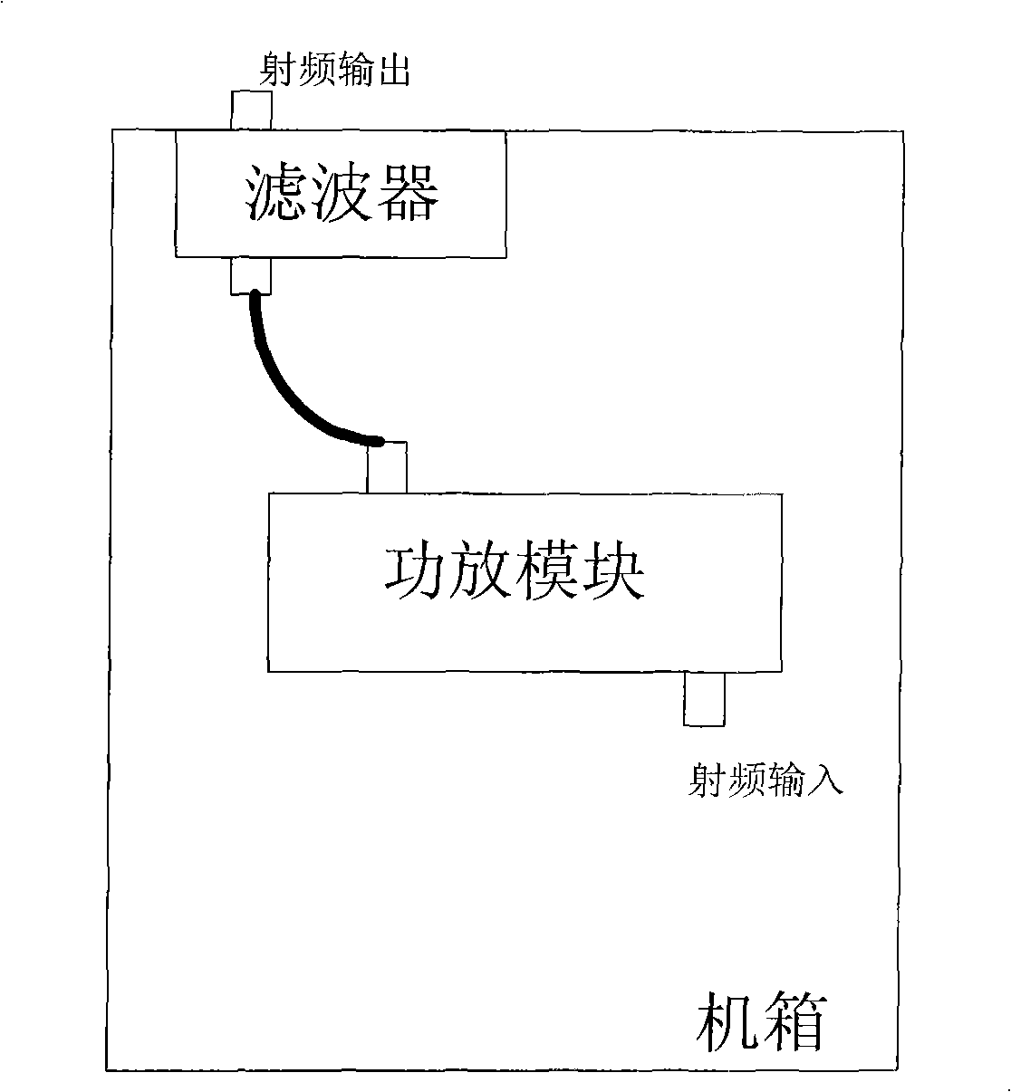
[0002] like figure 1 As shown, it is a structural schematic diagram of a radio frequency communication device in the prior art, which includes a chassis, and a power amplifier module and a filter installed in the chassis, wherein the power amplifier module and the filter are connected through a radio frequency cable. In the existing design 1. During the installation process, the power amplifier module and filter are usually set separately. When assembling, put the power amplifier module and filter into the chassis and then connect them through radio frequency cables. According to this radio frequency communication device in the prior art , because the power amplifier module and the filter are connected by radio frequency cables, and the impedance of the radio frequency cables themselves will inevitably cause losses to the transmission of radio frequency signals, resulting in unnecessary signal loss, and this The loss is usually 0.2dB or more, which increases the performance requirements of the power amplifier and increases the difficulty of debugging the power amplifier. In addition, because the power amplifier module and the filter are connected by radio frequency cables, and the radio frequency cables are in the chassis The coiled direction will make the overall layout messy, reducing the compactness and aesthetics of the overall layout of the device

Method used


Image

  • Radio communication equipment
  • Radio communication equipment
  • Radio communication equipment

Examples


Embodiment Construction

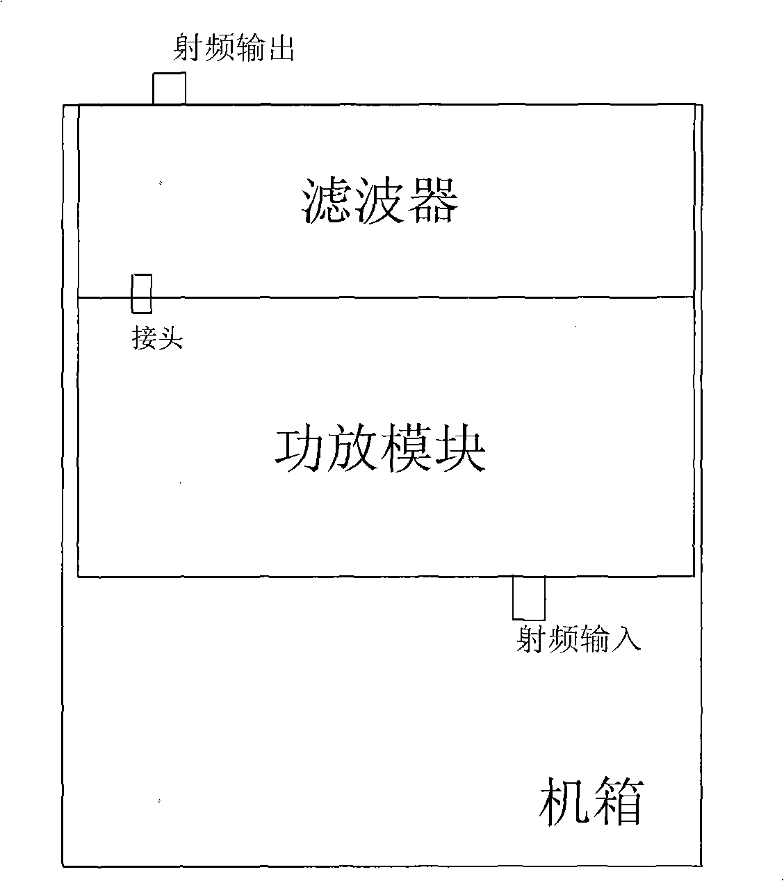
[0014] Such as figure 2 As shown, it is a schematic structural diagram of an embodiment of a radio frequency communication device of the present invention, which includes a chassis, a power amplifier module, a filter, and a connecting joint, wherein the power amplifier module, the filter, and the connecting joint are arranged in the chassis, and one end of the connecting joint is connected to the The power amplifier module is directly connected, and the other end is directly connected to the filter.

[0015] According to the above-mentioned radio frequency communication device of the present invention, the power amplifier module and the filter are directly connected through the connection joint, and after the radio frequency input signal enters the power amplifier module for amplification, it directly enters the filter through the connection joint for filtering. Compared with the prior art For the solution of connecting through radio frequency cables, it effectively avoids th...


PUM


Abstract

A radio frequency communication device comprises machine case, power amplifier module, filter, adapter one end of which is directly connected with power amplifier module, the other end of which is connected with filter. The power amplifier module and filter is installed in machine case, and the bottom plate of power amplifier module and filter is integrated with the machine case. The power amplifier module is directly connected with filter by adapter, which effectively avoids signal spoilage resulting from radio frequency cable adopted by existing technology and coil direction of radio frequency cable in machine case which makes device more compact and beautiful. The integral design effectively reduces cost, size and weight of radio frequency communication device.

Description

technical field [0001] The invention relates to the technical field of wireless communication, in particular to a radio frequency communication device. Background technique [0002] Such as figure 1 As shown, it is a structural schematic diagram of a radio frequency communication device in the prior art, which includes a chassis, and a power amplifier module and a filter installed in the chassis, wherein the power amplifier module and the filter are connected through a radio frequency cable. In the existing design 1. During the installation process, the power amplifier module and filter are usually set separately. When assembling, put the power amplifier module and filter into the chassis and then connect them through radio frequency cables. According to this radio frequency communication device in the prior art , because the power amplifier module and the filter are connected by radio frequency cables, and the impedance of the radio frequency cables themselves will inevita...

Claims


Application Information

Patent Timeline
IPC IPC(8): H04B7/00H04B1/02
Inventor 钟伟东刘兴现贺斌张跃军潘栓龙
Owner COMBA TELECOM SYST CHINA LTD
Learn More