Pneumatic tire assembly

A technology for pneumatic tires and components, applied in tire parts, with multiple inflatable chambers, with independent inflatable cushions, etc., can solve the problem of no solution provided, and achieve the effect of ensuring uniformity

Inactive Publication Date: 2009-01-21
TOYO TIRE & RUBBER CO LTD
View PDF9 Cites 11 Cited by
  • Summary
  • Abstract
  • Description
  • Claims
  • Application Information

AI Technical Summary

Problems solved by technology

However, Japanese Shikaihei No. 03-2801 communiqué does not provide a solution to the above-mentioned problems

Method used


Image

  • Pneumatic tire assembly
  • Pneumatic tire assembly
  • Pneumatic tire assembly

Examples


Embodiment Construction

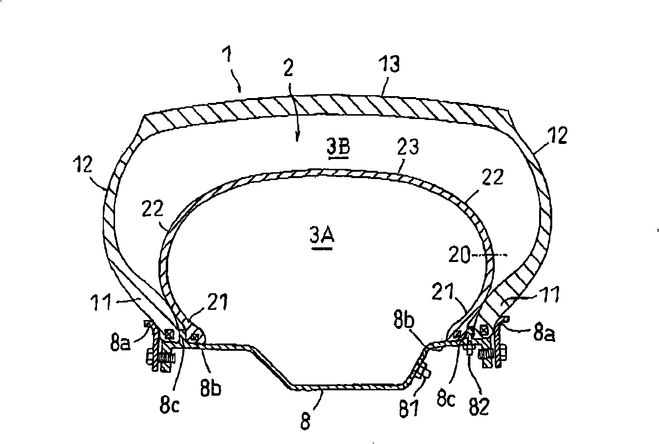
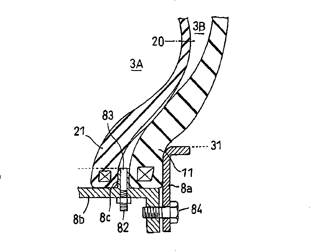
[0023] Embodiments of the present invention will now be described with reference to the accompanying drawings. figure 1 is a sectional view along a tire meridian showing an example of a pneumatic tire assembly according to the present invention. figure 2 yes figure 1 An enlarged view of the main part in .

[0024] Such as figure 1 and figure 2 As shown, the pneumatic tire assembly according to the present invention includes a rim 8 and a pneumatic tire having a double-layer structure consisting of a tire casing 1 and an inner tube 2 inserted into the casing and assembled with the rim 8 . The tire casing 1 is a tubeless tire including a pair of bead portions 11, sidewall portions 12 each extending outward in the tire diameter direction from the corresponding bead portions 11, and a tire disposed between the sidewall portions 12. The tread portion 13 . Likewise, the inner tube 12 is a tubeless tire including a pair of bead portions 21, sidewall portions 22 each extendi...


PUM


Abstract

A pneumatic tire assembly comprising a rim, a pneumatic tire that has a double structure including an outer tire and an inner tire inserted thereinto, and is assembled with the rim, and air chambers formed inside and outside the inner tire, wherein the rim includes a pair of bead seats on which bead portions of the outer tire and the inner tire are placed, a first rim flange protruding outward in a diameter direction of the tire from a side end of the bead seat, a second rim flange disposed inside the first rim flange in a rim width direction and formed on at least one of the bead seats while protruding therefrom, and an air valve provided to the second rim flange, the outer tire is held by the first rim flange and the second rim flange with the bead portion thereof being nipped therebetween, the inner tire is mounted with the bead portion thereof being in internal contact with the second rim flange, and in an outer wall surface area of the inner tire extending outward from a position of a maximum height of the second rim flange in a diameter direction of the tire, a groove portion for feeding air supplied via the air valve into the air chamber formed outside the inner tire is formed into a concave shape.

Description

technical field [0001] The present invention relates to a pneumatic tire assembly in which a double-layer structure pneumatic tire and a rim are assembled together, and the double-layer structure pneumatic tire includes an outer tire and an inner tire inserted into the outer tire. Background technique [0002] Figures 4 to 6 is a view showing an example of this type of conventional pneumatic tire assembly. The pneumatic tire included in this assembly has a double-layered structure of a tire 6 and an inner tire 7 . The tire case 6 has a bead portion 61 in contact with the inside of the rim flange 8a. The inner tube 7 is inserted into the tire case 6 and has a bead portion 71 in contact with the inside of the bead portion 61 of the tire case 6 . An air chamber 9A is formed inside the tube 7 , and an air chamber 9B is formed outside the tube 7 . The air chambers 9A and 9B are filled with air and are hermetically sealed independently of each other. [0003] In the above pne...

Claims


Application Information

Patent Timeline
Patent Type & Authority Applications(China)
IPC IPC(8): B60C5/02B60B21/10
CPCB60C17/01B60C5/22Y10T152/10594
Inventor 小原将明
Owner TOYO TIRE & RUBBER CO LTD
Why Eureka
Try Eureka