Method for controlling dehumidification rate and heat pump drier for implementing dehumidification rate control

A rate control, heat pump drying technology, applied in dryers, drying solid materials, drying gas layout, etc., can solve problems such as inability to achieve dehumidification rate, energy waste of equipment potential, and inability to achieve maximum dehumidification rate control.

Active Publication Date: 2009-01-21
GUANGDONG PROVINCE MODERN AGRI EQUIP RES INST
View PDF0 Cites 10 Cited by
  • Summary
  • Abstract
  • Description
  • Claims
  • Application Information

AI Technical Summary

Problems solved by technology

[0004] In the application of existing heat pump dryers, the air volume value G0 is difficult to accurately locate, so the maximum dehumidification rate control cannot be realized, and the control of the specified dehumidification rate cannot be realized. In addition, it will also cause waste of energy and bury the potential of the equipment

Method used


Image

  • Method for controlling dehumidification rate and heat pump drier for implementing dehumidification rate control

Examples


Embodiment Construction

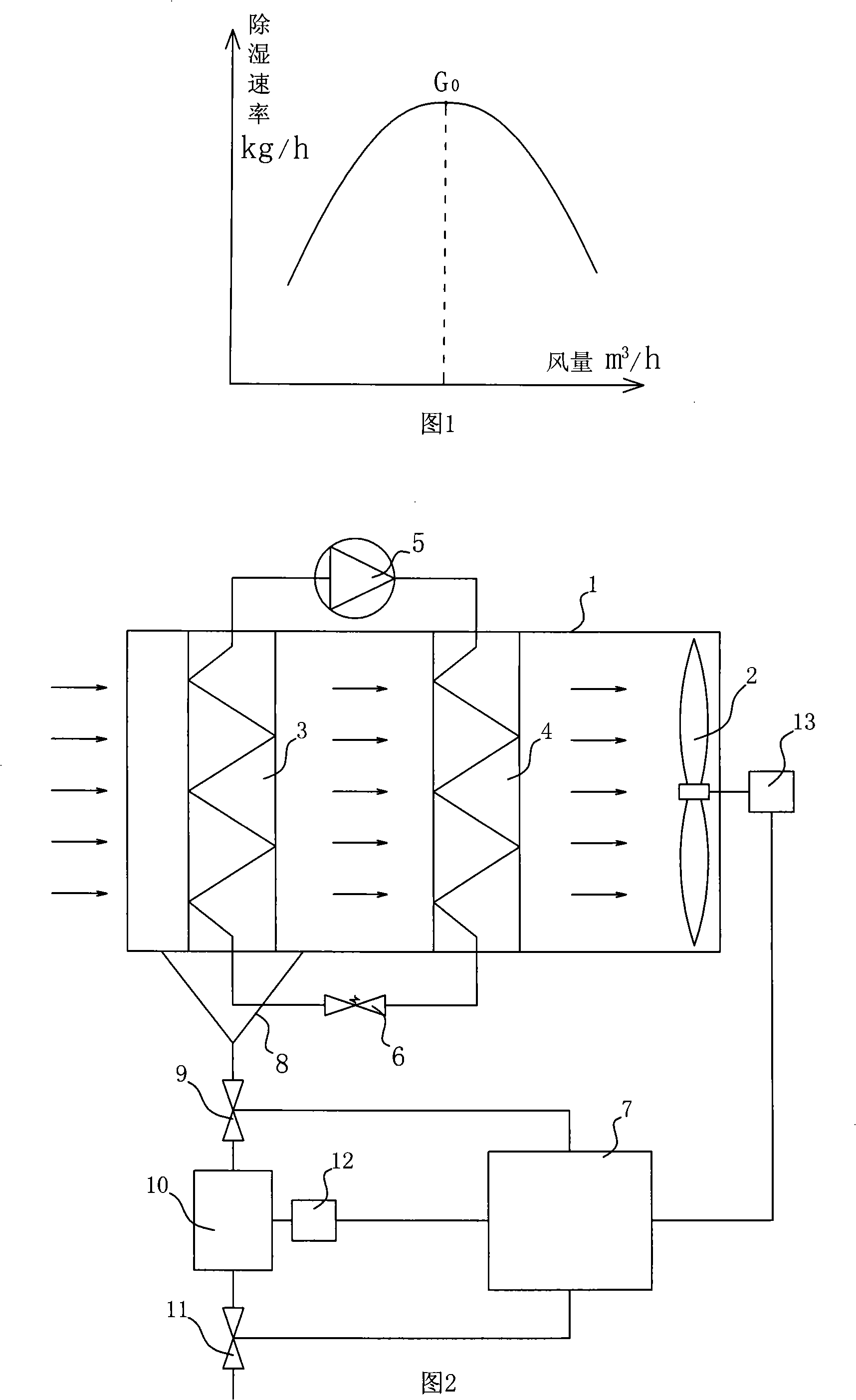
[0015] As shown in FIG. 1 , the heat pump dryer for realizing dehumidification rate control according to the present invention includes an airflow channel 1 , and a cooling device 3 and a heating device 4 are arranged in the airflow channel 1 . The cooling device 3 and the heating device 4 can be an evaporator and a condenser respectively, and a compressor 5 and an expansion valve 6 are connected between the evaporator and the condenser, and the evaporator, the condenser, the compressor 5, and the expansion valve 6 form a causative Cold medium circulation. The air flow channel 1 is provided with a fan 2 for making the air flow through the cooling device 3 and the heating device 4 in sequence. There is also a computer 7 and a water collector 8 that collects the condensed water of the cooling device 3. The water collector 8 can be a funnel located below the evaporator. When water condenses on the evaporator, the water will flow to the water collector. 8 in. The water collector...


PUM


Abstract

The invention discloses a dehumidification rate control method and a hot pump drier which can realize the control of the dehumidification rate. The dehumidification rate control method analyzes the relationships of latest results and historical date according to the relationships of blast volume and dehumidification capacity, and determines whether increases or reduces dehumidification blast volume. The invention can control the dehumidification rate in the drying process, can keep the hot pump direr operating under the state of the highest dehumidification rate or the appointed dehumidification rate at any time, and is suitable for the change of different material drying properties. The invention can save energy consumption, and fully develop the device potential of the hot pump drier.

Description

technical field [0001] The invention relates to a method for controlling the dehumidification rate of airflow drying, and also relates to a heat pump dryer capable of realizing the control of the dehumidification rate. Background technique [0002] At present, a common dryer generally has an airflow channel, and a cooling device and a heating device are arranged in the airflow channel. The cooling device and the heating device can be the evaporator and the condenser of the heat pump respectively. Fans for installations and heating installations. When in use, start the cooling device, heating device and fan. When the drying medium such as air flows through the cooling device, the water vapor in the drying medium will condense on the cooling device to achieve dehumidification, and then the drying medium will be heated by the heating device and released from the air flow flow out of the channel. This heat pump dryer can provide drying media with lower absolute humidity to dry...

Claims


Application Information

Patent Timeline
Patent Type & Authority Applications(China)
IPC IPC(8): F26B21/12F26B23/10F26B25/22
Inventor 李浩权吴耀森张进疆陈明刘清化赵锡和
Owner GUANGDONG PROVINCE MODERN AGRI EQUIP RES INST
Why Eureka
Try Eureka