Transform circuit adopting symmetrical cross-linked structure

A technology for converting circuits and cross-linking structures, applied in the field of converting circuits, can solve problems such as the lack of fundamental solutions, the deviation of the circuit from the high-efficiency working area, the expansion of device stress contradictions, etc., to achieve small internal resistance and loss, reduce voltage stress, application effect that works

Inactive Publication Date: 2012-05-23
李义
View PDF0 Cites 2 Cited by
  • Summary
  • Abstract
  • Description
  • Claims
  • Application Information

AI Technical Summary

Problems solved by technology

[0005] 2. The above problems are caused by the change of the voltage. With the increase of the voltage change ratio, the stress contradiction of the device will further expand, the circuit will deviate further from the high-efficiency working area, and the loss will increase sharply; moreover, a higher voltage change ratio will also lead to adjustment difficulties. , easy to get out of control
[0007] 3. Due to the asymmetric structure of the Boost and Buck converter circuits, the high-frequency and high-voltage signals generated by the high-frequency link will cause greater stress on the input and output filter links, and its radio frequency pollution is also very significant
Although the parallel interleaved technology that is currently being promoted can better solve the problem of differential mode filtering, it only achieves symmetry at the control level, and its circuit structure is still asymmetrical.
Other problems that may be caused by the asymmetry of the circuit structure have not been fundamentally solved

Method used


Image

  • Transform circuit adopting symmetrical cross-linked structure
  • Transform circuit adopting symmetrical cross-linked structure
  • Transform circuit adopting symmetrical cross-linked structure

Examples


Embodiment Construction

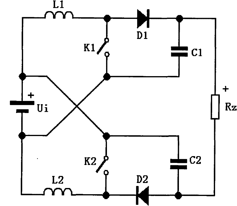
[0027] Further details will be given below in conjunction with the accompanying drawings and embodiments of the present invention.

[0028] see figure 1 , is a circuit structure schematic diagram of the first embodiment of a conversion circuit using a symmetrical cross-link structure in the present invention, that is, a symmetrical cross-link Boost conversion circuit. The conversion circuit includes a power supply Ui, a first inductor L1, a second inductor L2, a first diode D1, a second diode D2, a first capacitor C1, a second capacitor C2, a first switch K1, and a second switch K2 and load Rz. The positive pole of the power supply is connected to the negative pole of the power supply through the first inductor, the positive pole and the negative pole of the first diode, the positive pole and the negative pole of the load, the positive pole and the negative pole of the second diode, and the second inductor in turn. The terminal is connected between the positive pole of the l...


PUM


Abstract

The invention discloses a transform circuit adopting a symmetrical cross-linked structure, comprising two like transformers, and the two transformers are symmetrically cross-linked. In the invention, the transform circuit with the symmetrical cross-linked structure is adopted, thereby the voltage transmission ratio and the regulation performance of a Boost or Buck transformer are obviously improved, the voltage stress of power devices is obviously reduced, and the conversion efficiency of the transform circuit is equivalent to or higher than that of the Boost or Buck transformer within a larger application scope,.

Description

【Technical field】 [0001] The invention relates to the technical field of power electronics, in particular to a conversion circuit using a symmetrical cross-linked structure for Boost and Buck converters respectively. 【Background technique】 [0002] At present, conversion circuits including Boost converter (boost circuit) and Buck converter (step-down circuit) are the two most basic circuits in the field of power electronics application technology, and are the basis of other conversion circuits. At present, Boost and Buck converters are the most basic, classic, efficient and economical circuits for power converters. [0003] However, the prior art Boost and Buck converters have the following problems: [0004] 1. The main components must bear the asymmetric voltage and current stress from the input and output ports at the same time. Although if one port is high voltage, it must be low current, and the other port is the opposite, but we can only use high-voltage and high-cur...

Claims


Application Information

Patent Timeline
Patent Type & Authority Patents(China)
IPC IPC(8): H02M7/49
Inventor 李义
Owner 李义
Why Eureka
Try Eureka