Transform circuit adopting symmetrical cross-linked structure

A technology for converting circuits and cross-linked structures, which is applied in the field of converting circuits, can solve problems such as increased losses, current-voltage stress conflicts of power devices, and reduced conversion performance, so as to achieve small internal resistance and loss, increase power density, and reduce voltage stress. Effect

Inactive Publication Date: 2010-10-20
李义
View PDF5 Cites 15 Cited by
  • Summary
  • Abstract
  • Description
  • Claims
  • Application Information

AI Technical Summary

Problems solved by technology

Although one port is high voltage, then it must be low current, and the other port is the opposite, but we can only use high-voltage and high-current devices to meet the maximum stress of the current and voltage of the two ports at the same time.
This means that the device operates inefficiently and at high cost
Unfortunately, so far, various optimization improvements for Boost and Buck converters and the application of various new technologies including lossless absorption, soft switching and synchronous rectification technology have not made a breakthrough on this core issue.
[0005] 2. The above problems are caused by the change of the voltage. With the increase of the voltage change ratio, the stress contradiction of the device will further expand, the circuit will deviate further from the high-efficiency working area, and the loss will increase sharply; moreover, a higher voltage change ratio will also lead to adjustment difficulties. , easy to get out of control
There are also individual high-transformation-ratio direct conversion technologies that do not use transformers. Although they can make high-transformation ratios easier to realize, they still do not make current-voltage stress conflicts in power devices and adjustment difficult under high-transformation ratio conditions. Problem solved and less efficient
There is also a cascading technology proposed, trying to use the power relay of multiple single-stage circuits to achieve high transformation ratio output; the problem is, if adding a stage circuit means increasing stage loss, if reducing stage circuit means that the Other single-stage transformation ratios also increase losses; moreover, in the case of cascading multiple circuits, the contradiction between device stress selection, control and reliability of circuits at all levels is also difficult to compromise
In addition, the above-mentioned various methods for adapting to the application of a large voltage change ratio will reduce the conversion performance while satisfying the application of a lower voltage change ratio to varying degrees.
[0007] 3. Due to the asymmetric structure of the Boost and Buck converter circuits, the high-frequency and high-voltage signals generated by the high-frequency link will cause greater stress on the input and output filter links, and its radio frequency pollution is also very significant
Although the parallel interleaved technology that is currently being promoted can better solve the problem of differential mode filtering, it only achieves symmetry at the control level, and its circuit structure is still asymmetrical.
Other problems that may be caused by the asymmetry of the circuit structure have not been fundamentally solved

Method used


Image

  • Transform circuit adopting symmetrical cross-linked structure
  • Transform circuit adopting symmetrical cross-linked structure
  • Transform circuit adopting symmetrical cross-linked structure

Examples


Embodiment Construction

[0027] The following will further describe in detail with reference to the drawings and the embodiments of the present invention.

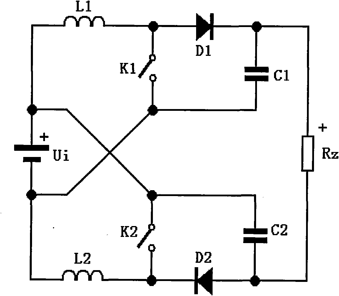
[0028] See figure 1 , Is a schematic diagram of the circuit structure of the first embodiment of a conversion circuit adopting a symmetrical cross-linked structure of the present invention, that is, a symmetrical cross-linked Boost conversion circuit. The conversion circuit includes a power supply Ui, a first inductor L1, a second inductor L2, a first diode D1, a second diode D2, a first capacitor C1, a second capacitor C2, a first switch K1, and a second switch K2 And load Rz. The positive pole of the power supply is connected to the negative pole of the power supply via the first inductor, the positive pole and negative pole of the first diode, the positive pole and negative pole of the load, the positive pole and negative pole of the second diode, and the second inductor to the negative pole of the power supply in turn. The terminal is connected ...


PUM


Abstract

The invention discloses a transform circuit adopting a symmetrical cross-linked structure, comprising two like transformers, and the two transformers are symmetrically cross-linked. In the invention, the transform circuit with the symmetrical cross-linked structure is adopted, thereby the voltage transmission ratio and the regulation performance of a Boost or Buck transformer are obviously improved, the voltage stress of power devices is obviously reduced, and the conversion efficiency of the transform circuit is equivalent to or higher than that of the Boost or Buck transformer within a larger application scope,.

Description

【Technical Field】 [0001] The invention relates to the technical field of power electronics, in particular to a conversion circuit adopting a symmetrical cross-linked structure for Boost and Buck converters respectively. 【Background technique】 [0002] At present, conversion circuits including Boost converter (boost circuit) and Buck converter (buck converter) are the two most basic circuits in the field of power electronics application technology, and are the basis of other conversion circuits. At present, Boost and Buck converters are the most basic, classic, efficient and economical circuits of power converters. [0003] However, the prior art Boost and Buck converters have the following problems: [0004] 1. The main components must simultaneously bear the asymmetrical voltage and current stress from the input and output ports. Although one port must have a low current if it has a high voltage, and the other port is the opposite, we can only use high-voltage and high-current dev...

Claims


Application Information

Patent Timeline
Patent Type & Authority Applications(China)
IPC IPC(8): H02M7/49
Inventor 李义
Owner 李义
Why Eureka
Try Eureka