Backlight system and light guide board with micro-optical structure

A backlight system and micro-optical technology, applied in the direction of light guide, optics, optical components, etc., can solve the problems of poor light-gathering effect and low utilization rate of light energy, and achieve the effect of reducing the number of components, reducing costs, and achieving high integration

Inactive Publication Date: 2009-01-21
SHENZHEN UNIV +1
View PDF1 Cites 14 Cited by
  • Summary
  • Abstract
  • Description
  • Claims
  • Application Information

AI Technical Summary

Problems solved by technology

[0005] In order to solve the technical problem that the light-concentrating effect of the V-shaped prism structure on the light-emitting surface of the light guide plate in the prior art is poor, resulting in low light energy utilization, the present invention provides a light guide that can increase the light energy utilization and improve the light-concentrating effect. Light plate and backlight module using the light guide plate

Method used


Image

  • Backlight system and light guide board with micro-optical structure
  • Backlight system and light guide board with micro-optical structure
  • Backlight system and light guide board with micro-optical structure

Examples


Embodiment Construction

[0028] Below in conjunction with accompanying drawing and embodiment the utility model is further described.

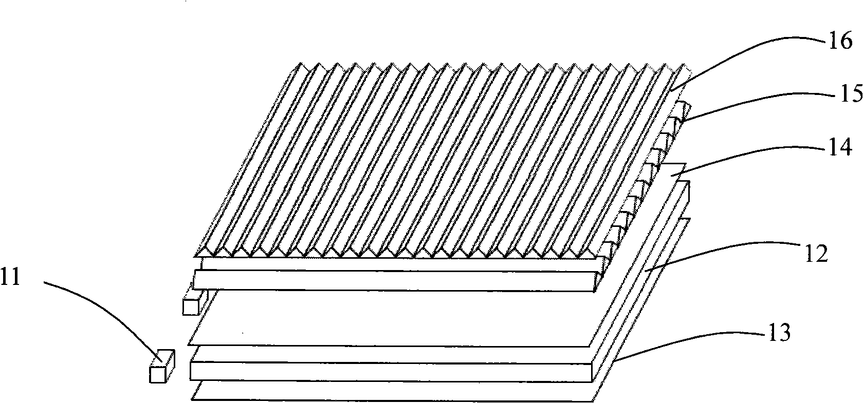
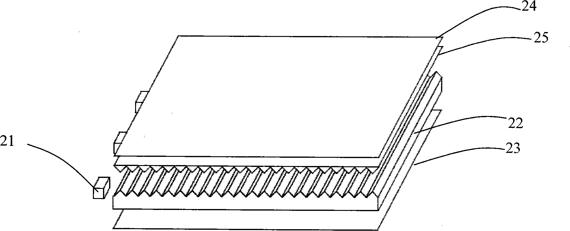
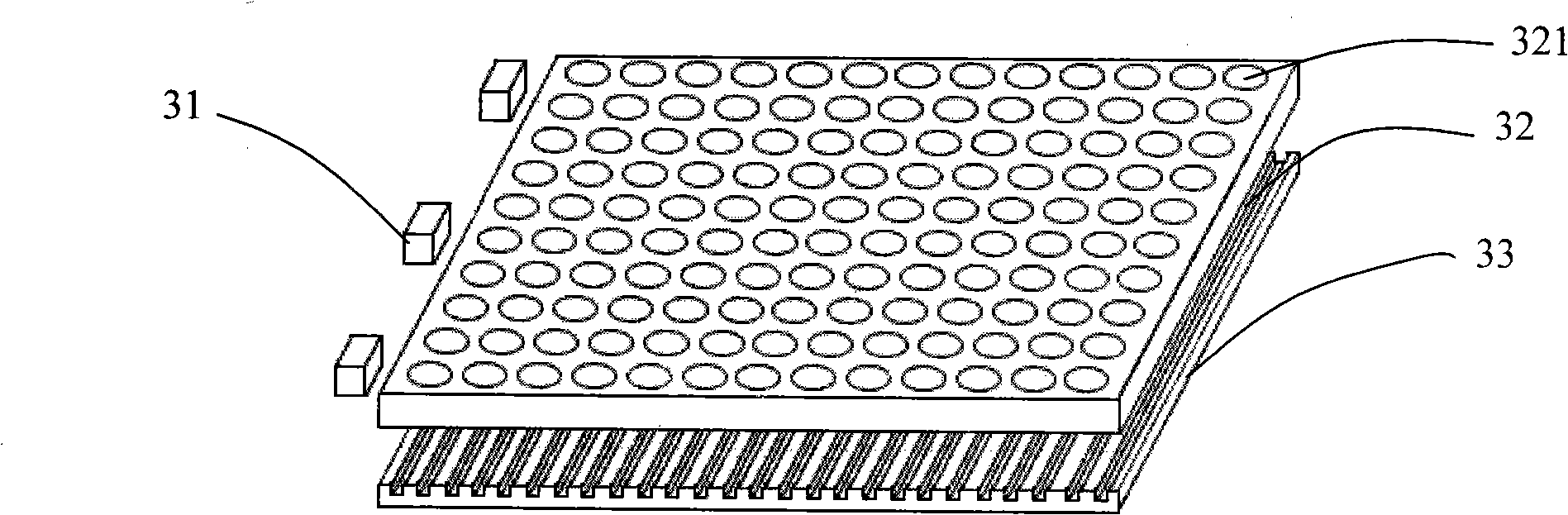
[0029] Such as Figure 3 ~ Figure 8 as shown, image 3 It is a structural schematic diagram of an embodiment of the present invention having a backlight system with a micro-optical structure and a light guide plate. The backlight system of this embodiment includes: a light source 31 , a light guide plate 32 and a reflection sheet 33 . Wherein, the light guide plate 32 includes a light incident surface for receiving the light emitted by the light source 31, a light exit surface for emitting the light, and a bottom surface opposite to the light exit surface, and a micro-optical light concentrating structure 321 is arranged on the light exit surface of the light guide plate 32. , Figure 4 That is, a structural schematic diagram of the micro-optical light-concentrating structure 321 having a concave region at the top, Figure 5 is a schematic cross-sectional view of ...


PUM

PropertyMeasurementUnit
widthaaaaaaaaaa
widthaaaaaaaaaa

Abstract

The invention relates to a micro optical backlight system, comprising a light guide plate composed of an incident surface, an emergence surface and a bottom opposite to the emergence surface; a light source near the incident surface; and a reflector near the bottom, wherein the emergence surface of the light guide plate is provided with a micro optical condensation structure with a top concave area. The invention further relates to a light guide plate comprising an incident surface, an emergence surface and a bottom opposite to the emergence surface, wherein the emergence surface is provided with a micro optical condensation structure with a top concave area. The micro optical condensation structure with a top concave area can condense emergent lights to improve the light utilization of the system. The backlight system is combined with a reflector of micro reflection structure to utilize the micro reflection structure of the reflector and the micro optical condensation structure of the emergence surface of the light guide plate to adjust the emergent lights of the light guide plate to an ideal vision field. The invention eliminates traditional prisms, reduces element number, realizes high integrality, improves light utilization and reduces cost.

Description

【Technical field】 [0001] The invention relates to a micro-optic structure backlight system and a light guide plate, in particular to a micro-optic structure backlight system and a light guide plate for passive luminescent flat panel display. 【Background technique】 [0002] Existing passive light-emitting flat-panel display devices, such as liquid crystal displays (Light crystal displays, LCDs), have the advantages of light weight, thin thickness, low energy consumption, and no radiation, so they are widely used in mobile phones, digital cameras, video cameras, mp3 and other products. Since the liquid crystal material itself does not have light-emitting properties, it is necessary to provide it with an additional light source to realize the display function. [0003] Such as figure 1 As shown, it is a structural schematic diagram of an existing backlight system involved in US6443583 announced by 3M Company of the United States on September 3, 2002. The backlight system incl...

Claims


Application Information

Patent Timeline
Patent Type & Authority Applications(China)
IPC IPC(8): G02F1/13357G02B6/00G02F1/1335
Inventor 徐平黄洁锋
Owner SHENZHEN UNIV
Why Eureka
Try Eureka