
Backlight module unit and optical plate thereof

A technology of backlight module and optical plate, applied in optics, optical components, nonlinear optics, etc., can solve the problem of uneven light output of backlight module 100

Inactive Publication Date: 2009-01-21
HONG FU JIN PRECISION IND (SHENZHEN) CO LTD +1
View PDF0 Cites 0 Cited by
  • Summary
  • Abstract
  • Description
  • Claims
  • Application Information

AI Technical Summary

Problems solved by technology

The matching design of the light-emitting diode 15 and the reflector 17 can reduce the bright area directly above the light-emitting diode 15 to a certain extent, but the backlight module 100 still has the disadvantage of uneven light output.

Method used


Image

  • Backlight module unit and optical plate thereof
  • Backlight module unit and optical plate thereof
  • Backlight module unit and optical plate thereof

Examples


Embodiment Construction

[0022] The backlight module and its optical board of the present invention will be further described in detail below with reference to the drawings and embodiments.

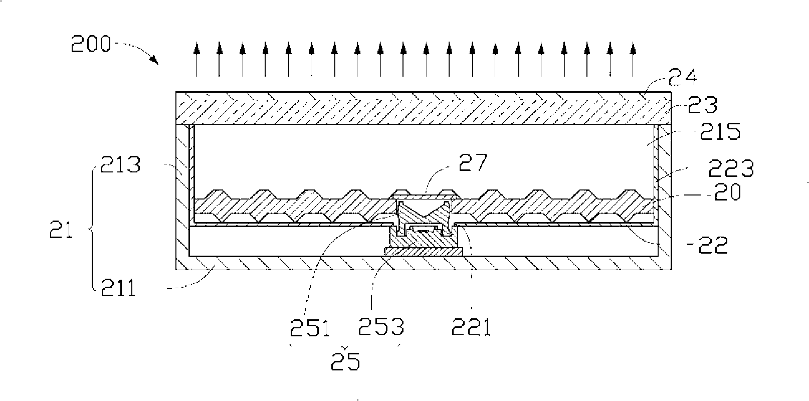
[0023] See figure 2 , shows the backlight module 200 of the preferred embodiment 1 of the present invention, which includes a frame 21 , a reflector 22 , a diffuser 23 , an edge-type point light source 25 , and an optical plate 20 . The frame 21 includes a rectangular bottom plate 211 and four sidewalls 213 vertically extending from the edge of the bottom plate 211 to the same side thereof and connected to each other. The four side walls 213 together with the bottom plate 211 form a cavity 215 . The diffuser plate 23 is disposed on top of the plurality of sidewalls 213 for covering the cavity 215 . The cavity 215 can accommodate components such as the point light source 25 , the reflection plate 22 and the optical plate 20 . The light emitted from the point light source 25 can be emitted through the diffuser ...


PUM


Abstract

An optical board comprises at least one optical board unit comprising a first surface and a second surface opposite to the first surface, wherein the first surface is formed with a plurality of sealed V-shaped protrusions, the second surface is formed with a plurality of micro protrusions, the section of each micro protrusion parallel with the bottom surface is round, whose diameter is reduced gradually from the bottom surface, at least one of the first and the second surfaces is provided with a light source containing part. The invention provides a backlight module group adopting the optical board, having uniform emergent lights.

Description

technical field [0001] The invention relates to a backlight module and its optical board, in particular to a backlight module for liquid crystal display and its optical board. Background technique [0002] Since the liquid crystal itself of the liquid crystal display panel does not have light-emitting properties, it is necessary to provide a light source device, such as a backlight module, for the liquid crystal display panel in order to achieve a display effect. The function of the backlight module is to supply a surface light source with sufficient brightness and uniform distribution to the LCD panel. [0003] See figure 1 , shows a conventional backlight module 100 , which includes a frame 11 , a reflector 12 , a diffuser 13 , a prism sheet 14 and a light emitting diode 15 . The frame 11 includes a rectangular bottom plate 111 and four sidewalls 113 vertically extending from the edge of the bottom plate 111 to the same side thereof. The bottom plate 111 and the four si...

Claims


Application Information

Patent Timeline
Patent Type & Authority Applications(China)
IPC IPC(8): G02F1/13357G02F1/1335
CPCG02F1/133603G02F1/133606G02B6/0031G02B6/0036G02F2001/133607G02B6/0055G02B6/0021G02F1/133607
Inventor 章绍汉
Owner HONG FU JIN PRECISION IND (SHENZHEN) CO LTD
Features
  • Generate Ideas
  • Intellectual Property
  • Life Sciences
  • Materials
  • Tech Scout
  • Unparalleled Data Quality
  • Higher Quality Content
  • 60% Fewer Hallucinations
Learn More