
Transfer plate

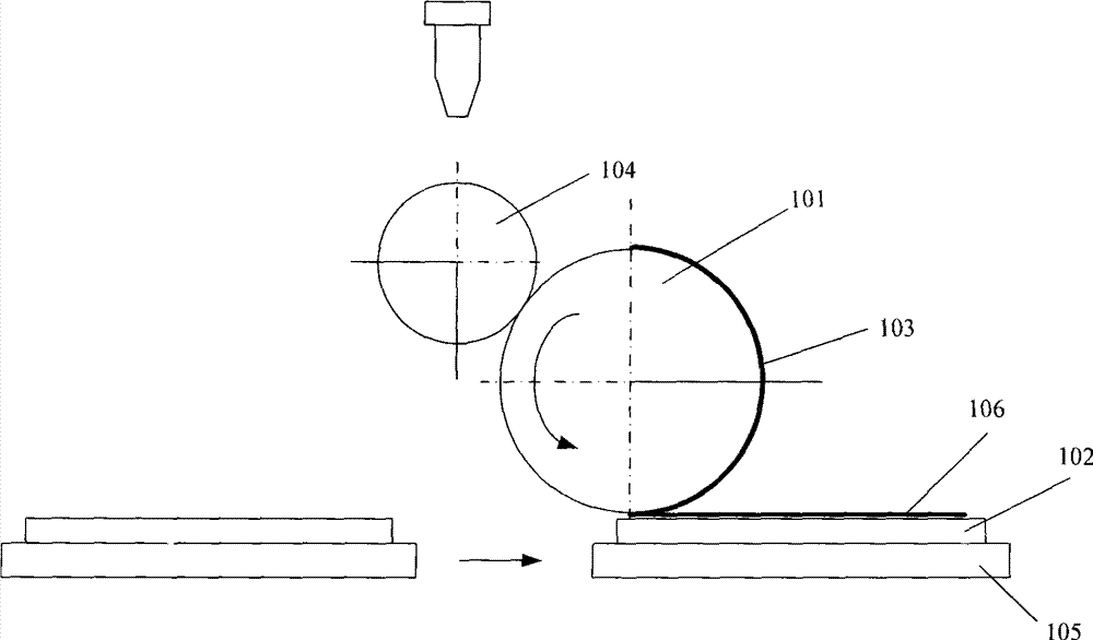
A technology for transfer plates and substrates, applied in printing, copying/marking methods, instruments, etc., can solve problems such as waste of PI liquid, and achieve the effect of ensuring quality

Active Publication Date: 2012-11-21
K TRONICS (SUZHOU) TECH CO LTD +1
View PDF1 Cites 0 Cited by
  • Summary
  • Abstract
  • Description
  • Claims
  • Application Information

AI Technical Summary

Problems solved by technology

[0012] It can be seen from the above technical scheme that the present invention adopts the technical means of adding blank blocks in the dummy blocks, which overcomes the technical problem that the PI liquid printed on the dummy blocks is completely wasted, and at the same time reasonably involves the difference between the blank blocks and the dummy blocks. distribution, to ensure the effect of printing and subsequent rubbing orientation operations, and to ensure the quality of the product

Method used


Image

  • Transfer plate
  • Transfer plate
  • Transfer plate

Examples


Embodiment Construction

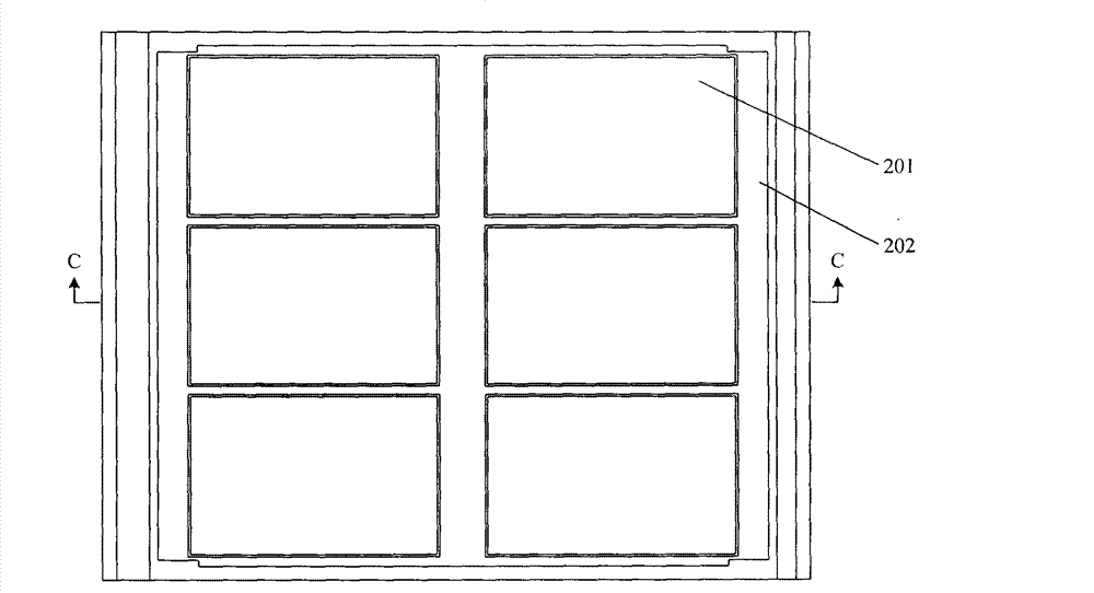
[0025] Such as Figure 3A Shown is the top view of the specific embodiment 1 of the transfer plate of the present invention. This embodiment is a PI transfer plate applied to printing PI liquid on the glass substrate of a thin film liquid crystal tube liquid crystal display. The transfer plate includes a substrate 1, the substrate Several display panel blocks 2 are arranged on 1, and a dummy block 3 is formed between several display panel blocks 2, wherein a blank block 4 is set in the dummy block 3 perpendicular to the printing direction A of the substrate 1, Such as Figure 3B shown as Figure 3A The C-C cross-section diagram, Figure 3C for Figure 3B A partial enlarged view of Figure 3B It can be seen that the upper surface of the blank block 4 is lower than the upper surface of the dummy block 3, further, the depth of the blank block 4 can be the same as the depth of the blank block at the edge of the printing area of ​​the substrate 1 of the transfer plate same.

...


PUM

PropertyMeasurementUnit
radiusaaaaaaaaaa
radiusaaaaaaaaaa

Abstract

The invention relates to a transfer printing plate, in particular to a transfer printing plate used for printing polyimide solution on the glass substrate of a film transistor LCD. The transfer printing plate comprises a substrate which is provided with a plurality of display panel image blocks; virtual image blocks are formed between the display panel image blocks, wherein, a blank image block is arranged in the virtual image blocks in a direction vertical to the printing direction of the substrate; the upper surface of the blank image block is lower than the upper surface of the virtual image block. The transfer printing plate can reduce the waste on the polyimide during the printing process, reduces the cost of the product, can avoid the poor effects generated in the printing and friction process and ensure the quality of the product.

Description

technical field [0001] The invention relates to a transfer printing plate, in particular to a transfer printing plate for printing polyimide liquid on a glass substrate of a thin film liquid crystal tube liquid crystal display. Background technique [0002] In the liquid crystal display panel of Thin Film Transistor-Liquid Crystal Display (hereinafter referred to as TFT LCD), on the array (ARRAY) substrate behind each three primary colors (Red, Green, Blue, referred to as RGB) sub-pixel, All have a corresponding TFT circuit. After applying a voltage, the liquid crystal molecules between the TFT and the color filter pixel are deflected, thereby controlling the rotation direction and polarization state of polarized light. In order to make these liquid crystal molecules in an ordered state before deflection and arrange them according to the design requirements, it is necessary to form an alignment film on the display panel area on the array substrate and the color filter (C / F) ...

Claims


Application Information

Patent Timeline
Patent Type & Authority Patents(China)
IPC IPC(8): G02F1/1337G02F1/1333B41M5/00
Inventor 陈东董学金镇满
Owner K TRONICS (SUZHOU) TECH CO LTD
Learn More