Vacuum switch contact

A vacuum switch and contact technology, applied in the electrical field, can solve the problems of high possibility of re-ignition and insufficient withstand voltage, and achieve the effect of reducing arc voltage, reducing the possibility of re-ignition, and satisfying high-voltage breaking.

Inactive Publication Date: 2009-02-04
韩玉杰
View PDF0 Cites 4 Cited by
  • Summary
  • Abstract
  • Description
  • Claims
  • Application Information

AI Technical Summary

Problems solved by technology

However, the current vacuum switch contacts are often difficult to form a good longitudinal magnetic field for arc suppression due to the limitation of the structural shape, and it is difficult to solve the problems of electric field concentration, insufficient withstand voltage and high possibility of re-ignition during high-voltage breaking.
For the breaking of high-voltage circuits, the existing technology can realize the breaking of 36 kV voltage. For higher voltage circuits, especially the high voltage of 72 kV, there is no vacuum switch contact structure that can meet the requirements of effectively extinguishing when breaking. Arc requirements, which is one of the problems to be solved in the existing vacuum switch technology

Method used


Image

  • Vacuum switch contact
  • Vacuum switch contact
  • Vacuum switch contact

Examples


Embodiment 2

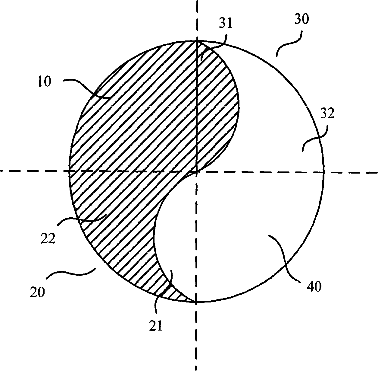
[0044] Such as figure 2 Shown is a cross-sectional view of the second embodiment of the vacuum switch contact of the present invention. The structure of this embodiment is roughly the same as that of the first embodiment, except that the first lower left area 21 and the first upper right area 31 are in the shape of a circular crown. And the straight long side of the first upper right area 31 is adjacent to the upper left area 10, and the straight long side of the first lower left area 21 is adjacent to the lower right area 40, as figure 2 shown.

[0045] The vacuum switch contact of this embodiment is similar to the working principle of the vacuum switch contact of Embodiment 1, which can provide an effective arc extinguishing longitudinal magnetic field, and the improvement of arc extinguishing ability is beneficial to reduce the possibility of restrike when the voltage is broken, and reduce the arc Therefore, it can meet the requirements of high-voltage breaking. The tech...

Embodiment 3

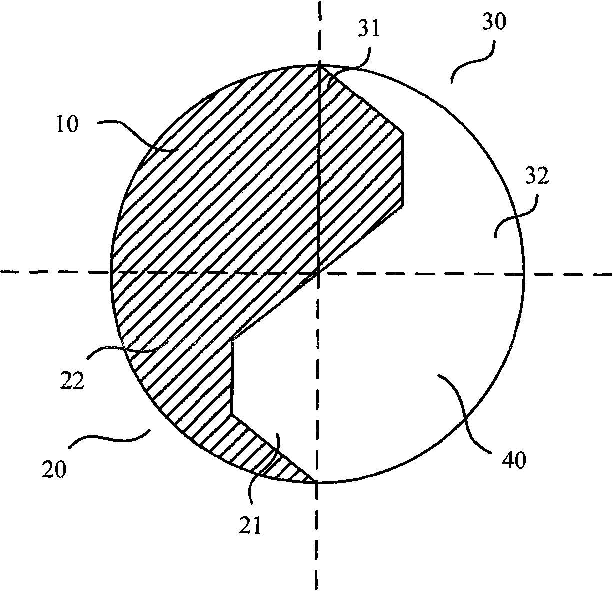
[0047] Such as image 3 Shown is the cross-sectional view of the third embodiment of the vacuum switch contact of the present invention. The structure of this embodiment is roughly the same as that of the first embodiment, except that the first lower left area 21 and the first upper right area 31 are trapezoidal in shape, and the first The bottom edge of the trapezoid of the upper right area 31, that is, the long side is adjacent to the upper left area 10, and the bottom edge of the trapezoid of the first lower left area 21, that is, the long side is adjacent to the lower right area 40, as image 3 shown.

[0048] The vacuum switch contact of this embodiment is similar to the working principle of the vacuum switch contact of Embodiment 1, which can provide an effective arc extinguishing longitudinal magnetic field, and the improvement of arc extinguishing ability is beneficial to reduce the possibility of restrike when the voltage is broken, and reduce the arc Therefore, it c...


PUM


Abstract

The invention relates to a vacuum switch contact, comprising an electric conduction assembly and a magnetic conduction assembly which extend along the same direction and are in abuttal joint with each other, making up the main body of the contact; wherein, the cross section of the magnetic conduction assembly is divided into a first section and a second section by a bit line of the magnetic conduction assembly, and the area of the first section is larger than that of the second section. Since one end of the vacuum switch contact is big and the other end is small, the magnetic field generated by the magnetic conduction assembly can flow into the main body of another contact because of the small space between the main bodies of the two contacts, thus providing a longitudinal magnetic field which can extinguish arc. The vacuum switch contact can reduce restrike possibility at the time of voltage disjunction, reduce arc voltage, and realize arc extinguishing and satisfy the requirement of high voltage disjunction.

Description

technical field [0001] The invention relates to a vacuum switch contact, in particular to a contact in an arc-extinguishing chamber of a vacuum switch tube, and belongs to the field of electrical technology. Background technique [0002] Switching equipment is a device that must be used in the circuit, and it plays the role of closing and breaking the circuit. During the breaking process of the two contacts in the switchgear, an arc will be generated, and the plasma arc with the arc column as the cone surface will be generated from the cathode spot combustion. Especially in high-voltage circuits, the arc generated between the switching contacts is particularly strong. [0003] The arc will increase the temperature of the switch and wear the switch, and the existence of the arc will reduce the current breaking capacity of the contacts. Therefore, the arc must be extinguished during the switching process of the switch contact. Most of the current switchgear uses such as oil...

Claims


Application Information

Patent Timeline
Patent Type & Authority Applications(China)
IPC IPC(8): H01H33/664H01H33/18H01H1/06
Inventor 韩玉杰
Owner 韩玉杰
Why Eureka
Try Eureka