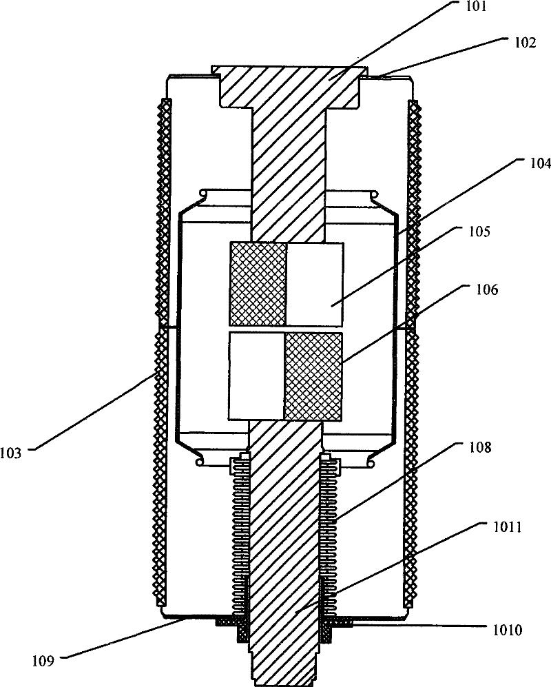
Vacuum switch tube

A vacuum switching tube and contact technology, which is applied in the electrical field, can solve the problems of insufficient withstand voltage and high possibility of restrike, and achieve the effect of reducing the possibility of restrike, reducing arc voltage, and satisfying high-voltage breaking

Active Publication Date: 2012-01-11
BEIJING BOE VACUUM ELECTRONICS CO LTD
View PDF0 Cites 0 Cited by
  • Summary
  • Abstract
  • Description
  • Claims
  • Application Information

AI Technical Summary

Problems solved by technology

However, the current vacuum switch contacts are often difficult to form a good longitudinal magnetic field for arc suppression due to the limitation of the structural shape, and it is difficult to solve the problems of electric field concentration, insufficient withstand voltage and high possibility of re-ignition during high-voltage breaking.
For the breaking of high-voltage circuits, the existing technology can realize the breaking of 36 kV voltage. For higher voltage circuits, especially the high voltage of 72 kV, there is currently no vacuum switching tube structure that can meet the requirements of effective arc extinguishing during breaking. requirements, which is one of the problems to be solved in the existing vacuum switch technology

Method used


Image

  • Vacuum switch tube
  • Vacuum switch tube
  • Vacuum switch tube

Examples


Embodiment 2

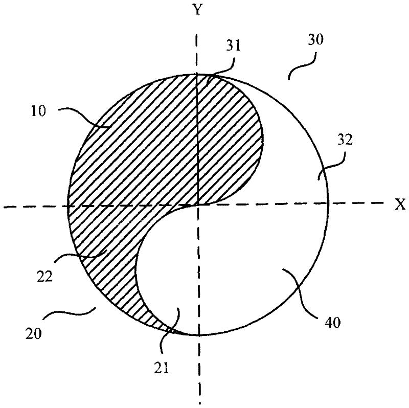
[0027] Such as image 3 Shown is a side view structural schematic diagram of the contact body in the second embodiment of the vacuum switch tube of the present invention. In this embodiment, the contact bodies of the first contact and the second contact are composed of several sheets stacked one after another. Taking the first contact as an example, each sheet is adjacent to a conductive sheet and a magnetically conductive sheet. Combined structure, several conductive sheets form a conductive part, and several magnetically conductive sheets form a magnetically conductive part, the cross-sectional shape of the conductive sheet and the magnetically conductive sheet and the structural relationship between the conductive part and the magnetically conductive part can adopt the above-mentioned embodiment. The technical solution is for the cooperation of yin and yang fish, and all the sheets are stacked together to form the outer contour shape of the main body of the contact, such as...

Embodiment 3

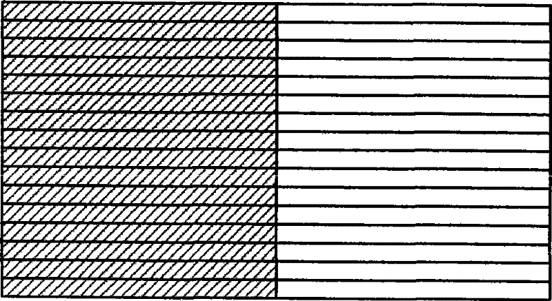
[0029] Such as Figure 4 Shown is a schematic diagram of the cross-sectional structure of the contact body in Embodiment 3 of the vacuum switch tube of the present invention. On the basis of the second embodiment above, in order to fix the relative position of the conductive part and the magnetic permeable part before the sheet body is melted and solidified, it is also possible to further set up a fixing mechanism that runs through several sheets on the conductive sheet 300 and the magnetically conductive sheet 400. hole 200, the fixing column 100 is inserted in the fixing hole 200, such as Figure 4 As shown, and one end of the fixing column 100 is fixed at the bottom inside the metal casing. The material of the fixing post 100 may be the same as that of the conductive component, such as copper metal.

[0030] The technical solution of this embodiment can simplify the production and manufacture of the contact body. After a plurality of sheet bodies are prepared by a simple ...


PUM


Abstract

The invention relates to a vacuum switch tube, comprising a first contact and a second contact which are respectively arranged on an electric conduction tube. The two contacts are cylindrical bodies and are sealed in a vacuum tube, face to face with each other. Each contact is composed of an electric conduction assembly and a magnetic conduction assembly, which extend along the same direction andare in abuttal joint with one another, making up the main body of the contact. The cross sections of the magnetic conduction assemblies and the electric conduction assemblies of first and second contacts are matched like Yin-Yang fish in shape. The magnetic conduction assembly of the first contact is arranged corresponding to the electric conduction assembly of the second contact, and the electric conduction assembly of the first contact is arranged corresponding to the magnetic conduction assembly of the second contact. The two contacts of the vacuum switch are anti-symmetrically arranged, therefore revolving magnetic fields, including a horizontal magnetic field and a vertical magnetic field with revolving magnetic lines of force, are formed between the two contacts of the vacuum switch, thus effectively reducing restrike possibility at the time of voltage disjunction and realizing arc extinguishing. The vacuum switch tube can satisfy the requirement of high voltage disjunction.

Description

technical field [0001] The invention relates to a vacuum switch tube, in particular to a vacuum switch tube with opposite contacts in an arc-extinguishing chamber, which belongs to the field of electrical technology. Background technique [0002] Switching equipment is a device that must be used in the circuit, and it plays the role of closing and breaking the circuit. During the breaking process of the two contacts in the switchgear, an arc will be generated, and the plasma arc with the arc column as the cone surface will be generated from the cathode spot combustion. Especially in high-voltage circuits, the arc generated between the switching contacts is particularly strong. [0003] The arc will increase the temperature of the switch and wear the switch, and the existence of the arc will reduce the current breaking capacity of the contacts. Therefore, the arc must be extinguished during the switching process of the switch contact. Most of the current switchgear uses me...

Claims


Application Information

Patent Timeline
Patent Type & Authority Patents(China)
IPC IPC(8): H01H33/66H01H33/664H01H33/18H01H1/06
Inventor 任建昌
Owner BEIJING BOE VACUUM ELECTRONICS CO LTD
Why Eureka
Try Eureka